Eureka AIR delivers breakthrough ideas for toughest innovation challenges, trusted by R&D personnel around the world.

Stirring cylinder of cold-regeneration stirring apparatus for asphalt mixture

A kind of asphalt mixture, cold recycling technology, applied in the direction of road, road repair, road, etc., can solve the problems of non-continuous feeding, difficult production, increased production cost, etc., to reduce labor intensity, facilitate cleaning of residual materials, The effect of ensuring uniformity

Inactive Publication Date: 2008-12-03
ZHENJIANG HUACHEN HUATONG ROAD MASCH CO LTD
View PDF2 Cites 8 Cited by
  • Summary
  • Abstract
  • Description
  • Claims
  • Application Information

AI Technical Summary

Problems solved by technology

The inner cavity of the old-fashioned mixing tank is formed by the intersection of two semi-cylindrical bodies. The upper end is the material inlet and the lower end is the material outlet. Such a mixing tank can only be stirred quantitatively. Continuous material supply is greatly limited in actual engineering. At the same time, this kind of mixing tank has a wear-resistant lining plate on the inner wall of the cylinder body. When stirring, the mixing blade directly acts on the wear-resistant lining plate to fully mix all materials. , because there is no gap between the blade and the liner, all materials are involved in the mixing, so the material mixing is relatively uniform
The mixing tank cavity is not only complex in shape and relatively difficult to manufacture, but also requires the use of wear-resistant linings, which increases production costs. Users must replace wear-resistant linings regularly during use, which also increases the cost of use.

Method used


Image

  • Stirring cylinder of cold-regeneration stirring apparatus for asphalt mixture
  • Stirring cylinder of cold-regeneration stirring apparatus for asphalt mixture
  • Stirring cylinder of cold-regeneration stirring apparatus for asphalt mixture

Examples


Embodiment Construction

[0020] Below in conjunction with accompanying drawing, the present invention is described in detail:

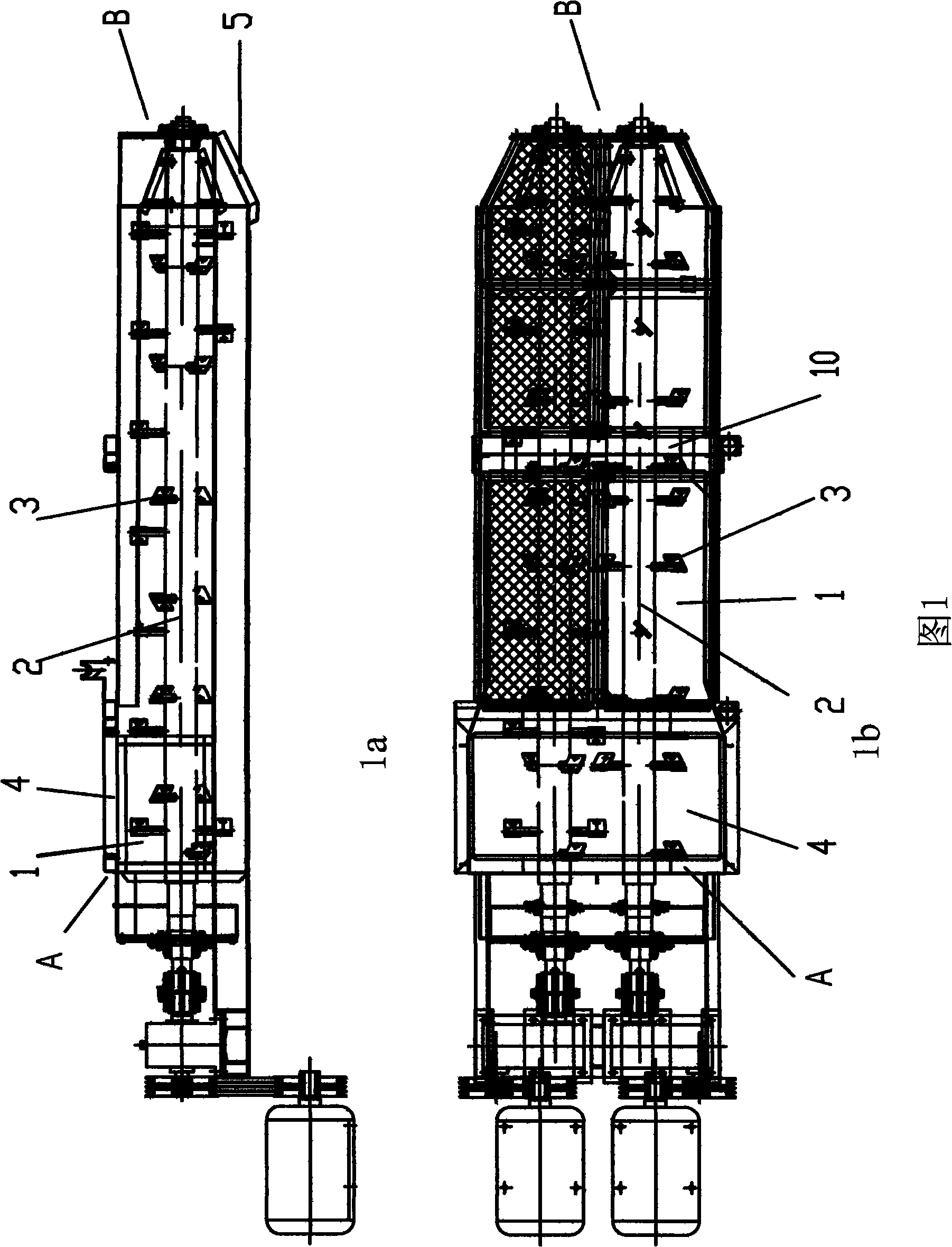
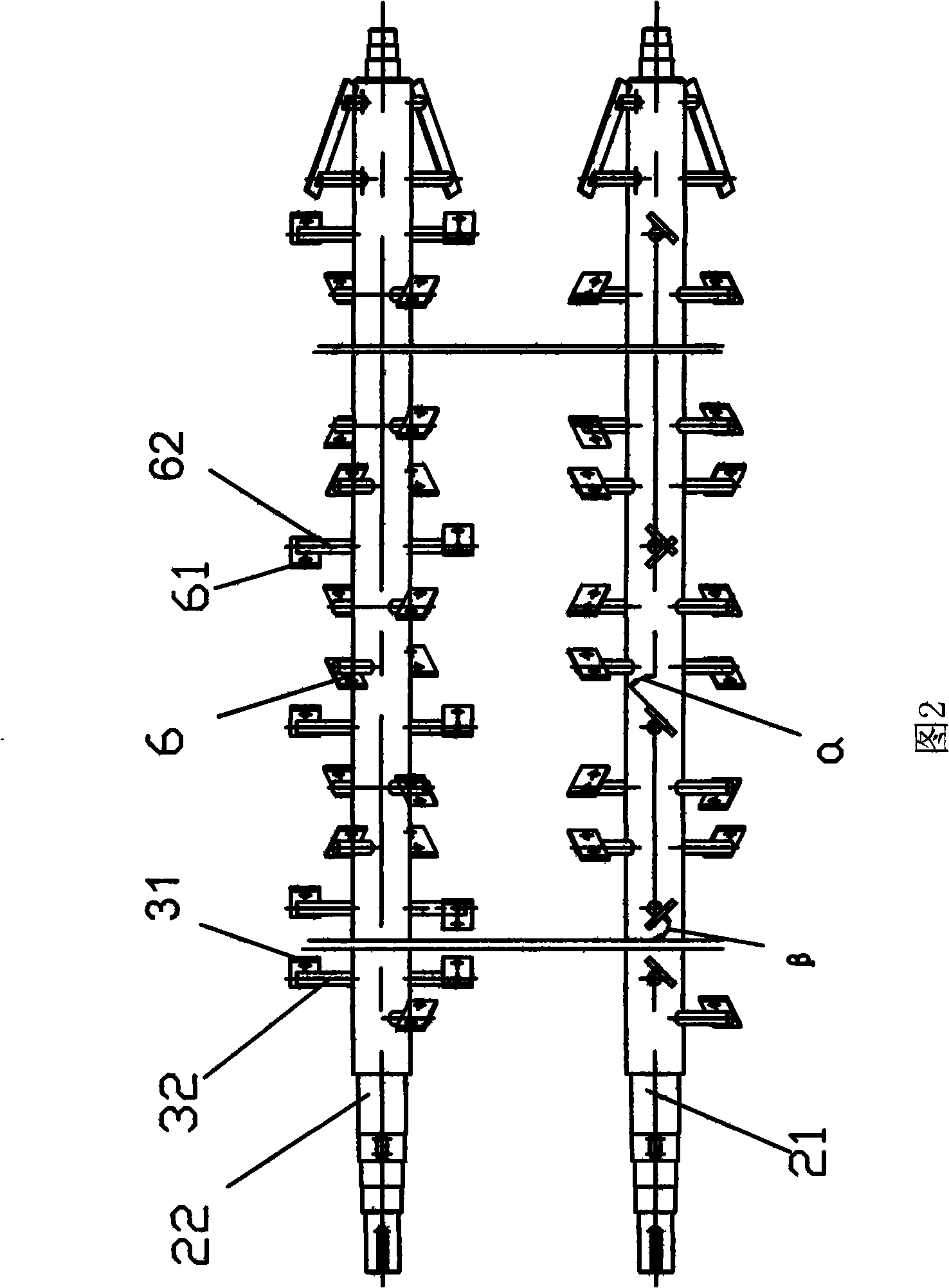
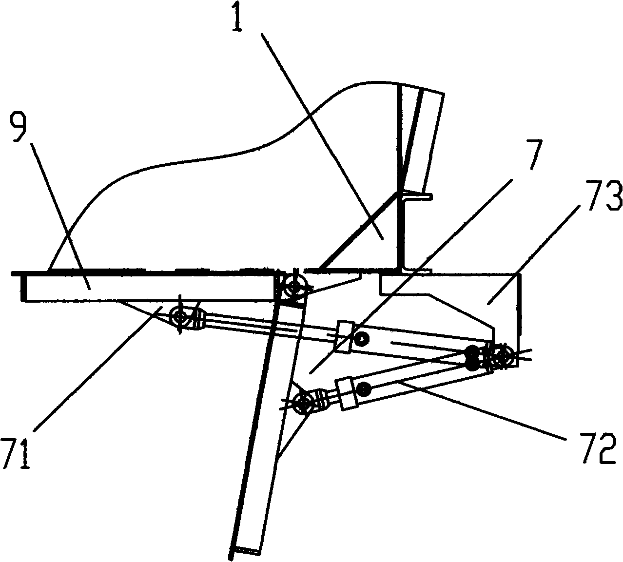
[0021] Referring to Figure 1- image 3 , the mixing tank of the present invention comprises a cylinder body 1, a material inlet 4 and a material outlet 5 are provided on the cylinder body 1, and the material inlet 4 is arranged on one axial end A of the cylinder body 1 stirring shaft 2 Above the end, the discharge port 5 is arranged below the other end B of the cylinder body 1 in the axial direction of the stirring shaft 2, and two rotatable stirring shafts 21, 22 are also arranged in the cylinder body 1, and the two stirring shafts 21, 22 Turning to the opposite, at least 3 stirring blade devices 3 are uniformly arranged respectively along the two stirring shafts 21, 22 axially, and the stirring blade device 3 includes a stirring blade 31 and a knife handle 32, and one end of the knife handle 32 is fixed on the stirring shaft On 21 and 22, the other end is connected to the b...


PUM


Abstract

The invention discloses an agitating tank of bituminous mixture cold regeneration and agitation equipment, which comprises a tank body and an inlet and an outlet formed on the tank body, wherein two rotatable agitating shafts are arranged inside the tank body; at least three agitating blade devices are arranged on each agitating shaft; each agitating blade device comprises an agitating blade and a holder; the inlet is formed above one end in the axial direction of the agitating shaft of the tank body; the outlet is formed below the other end in the axial direction of the agitating shaft of the tank body; and the plane of the agitating blade and the axial line of the agitating shaft form an included angle Alpha. Compared with the prior art, the inlet and the outlet of the tank body are formed on the two ends in the axial direction of the agitating shaft of the tank body; the agitating blades and the axial direction of the agitating shaft incline to form the included angle; materials to be agitated enter the inlet, are output from one end of the agitating shaft to the other end thereof in a mixed way under the agitating action of the inclined agitating blades, and meanwhile, during the agitating process, the agitating tank can realize continuous feeding after the materials to be agitated are mixed.

Description

technical field [0001] The invention relates to a mixing device, in particular to a mixing cylinder of a mixing equipment for cold regeneration of asphalt mixture. Background technique [0002] Asphalt mixture cold recycling mixing equipment is a mixing equipment used to process asphalt pavement milling materials, and the mixing tank is the heart part of the equipment. The milling material, water, cement, stone powder and emulsified asphalt are fully mixed in the mixing tank to become a qualified asphalt mixture. The inner cavity of the old-fashioned mixing tank is formed by the intersection of two semi-cylindrical bodies. The upper end is the material inlet and the lower end is the material outlet. Such a mixing tank can only be stirred quantitatively. Continuous material supply is greatly limited in actual engineering. At the same time, this kind of mixing tank has a wear-resistant lining plate on the inner wall of the cylinder body. When stirring, the mixing blade direct...

Claims


Application Information

Patent Timeline
Patent Type & Authority Applications(China)
IPC IPC(8): E01C19/10
Inventor 张伟栋刘耀光肖翀宇汤文龙华斌于怀义
Owner ZHENJIANG HUACHEN HUATONG ROAD MASCH CO LTD
Why Eureka
Eureka Blog
Learn More