Multi-test seat test station having in-turn arranged feeding section, test section and discharging section

A technology for testing machines and testing areas, which is applied to the testing of individual semiconductor devices, components of electrical measuring instruments, and electrical measurement. It can solve problems such as no simplification of the moving process, inability to improve the overall effect alone, and a sharp increase in manufacturing costs.

Active Publication Date: 2008-12-03
CHROMA ATE
View PDF0 Cites 12 Cited by
  • Summary
  • Abstract
  • Description
  • Claims
  • Application Information

AI Technical Summary

Problems solved by technology

[0012] Compared with the previous case, the material transfer device 34 of the previous case corresponds to the left cantilever pick-and-place device 13 of the earlier case, and is also responsible for moving the component to be tested from the feeding area to a transfer device, and from the transfer device After taking out the tested components to the discharge area, it is still necessary to use a single robot arm and suction nozzle to undertake all the feeding/discharging actions, and perform X-Y-Z three-direction movements, without any speed-up effect
[0013] As for the test part of the second half, although the previous proposal changed to use two sets of carrying mobile devices 33, 35 to distinguish the left and right, and six sets of pick-and-place mechanisms 331, 351 to drive the suction nozzles 332, 352, which can speed up the overall process at first glance; Above, the movement lines of each group of pick-and-place mechanisms and suction nozzles must be moved in the Y direction up and down in the figure and the Z direction of the lifting nozzle at the same time, and the complexity of the action itself has not been reduced.
What's more, wh

Method used


Image

  • Multi-test seat test station having in-turn arranged feeding section, test section and discharging section
  • Multi-test seat test station having in-turn arranged feeding section, test section and discharging section
  • Multi-test seat test station having in-turn arranged feeding section, test section and discharging section

Examples


Embodiment Construction

[0052] The foregoing and other technical contents, features and effects of the present invention will be clearly presented in the following detailed description of preferred embodiments with reference to the accompanying drawings. For convenience of description, the feeding device, the discharging device and the driving device 72 of the detection machine of the present invention are all taken as an example of a screw.

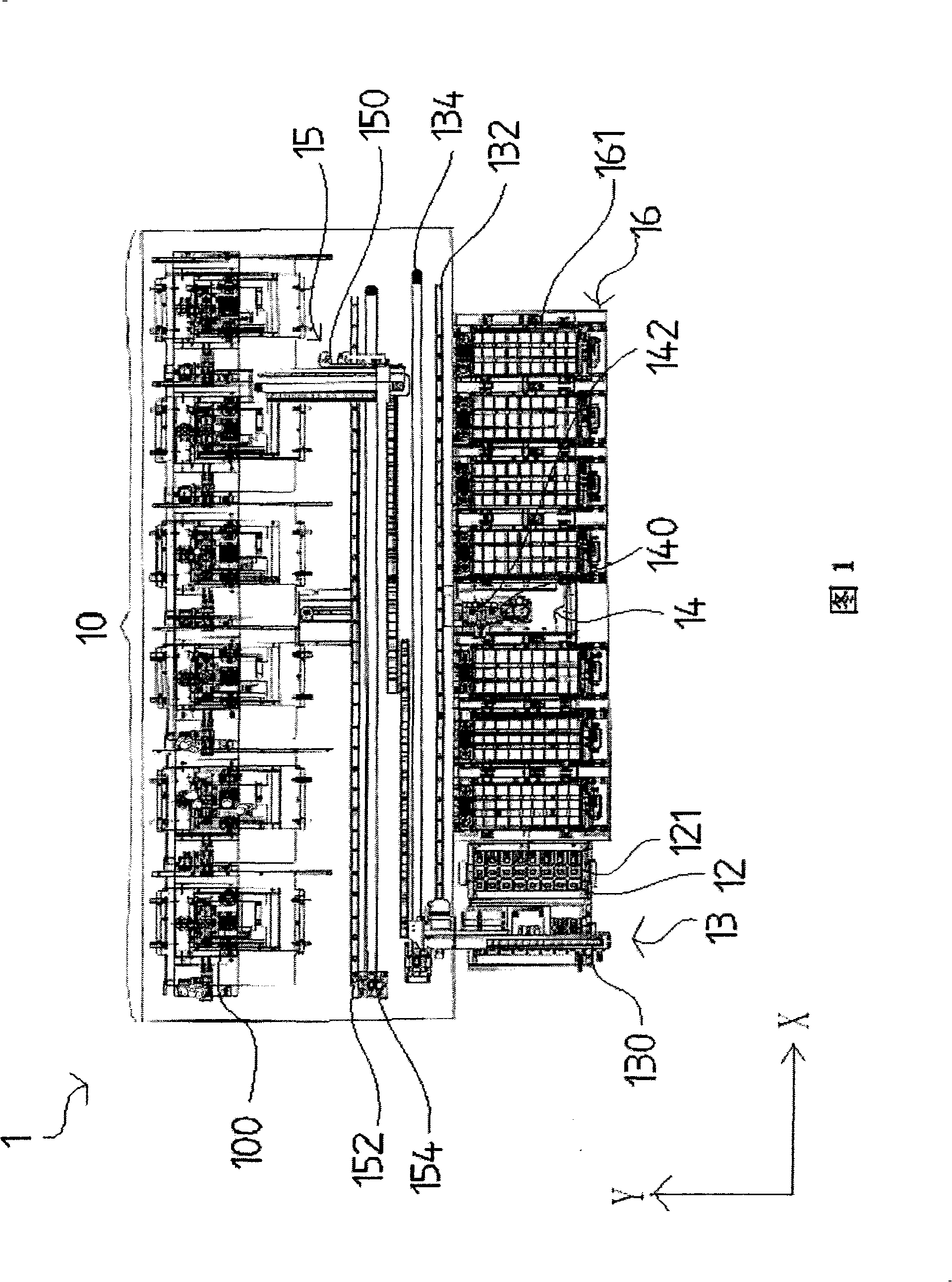
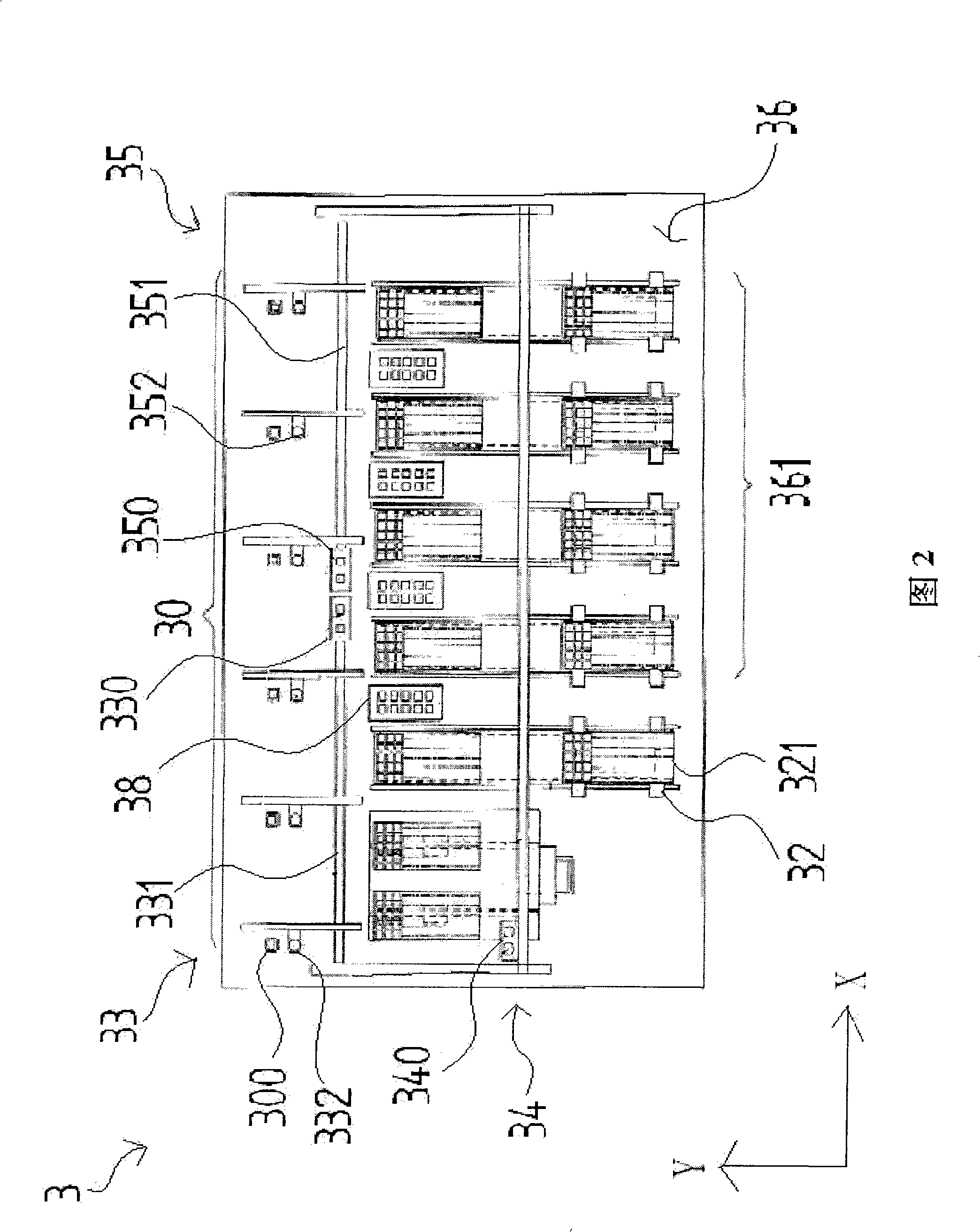
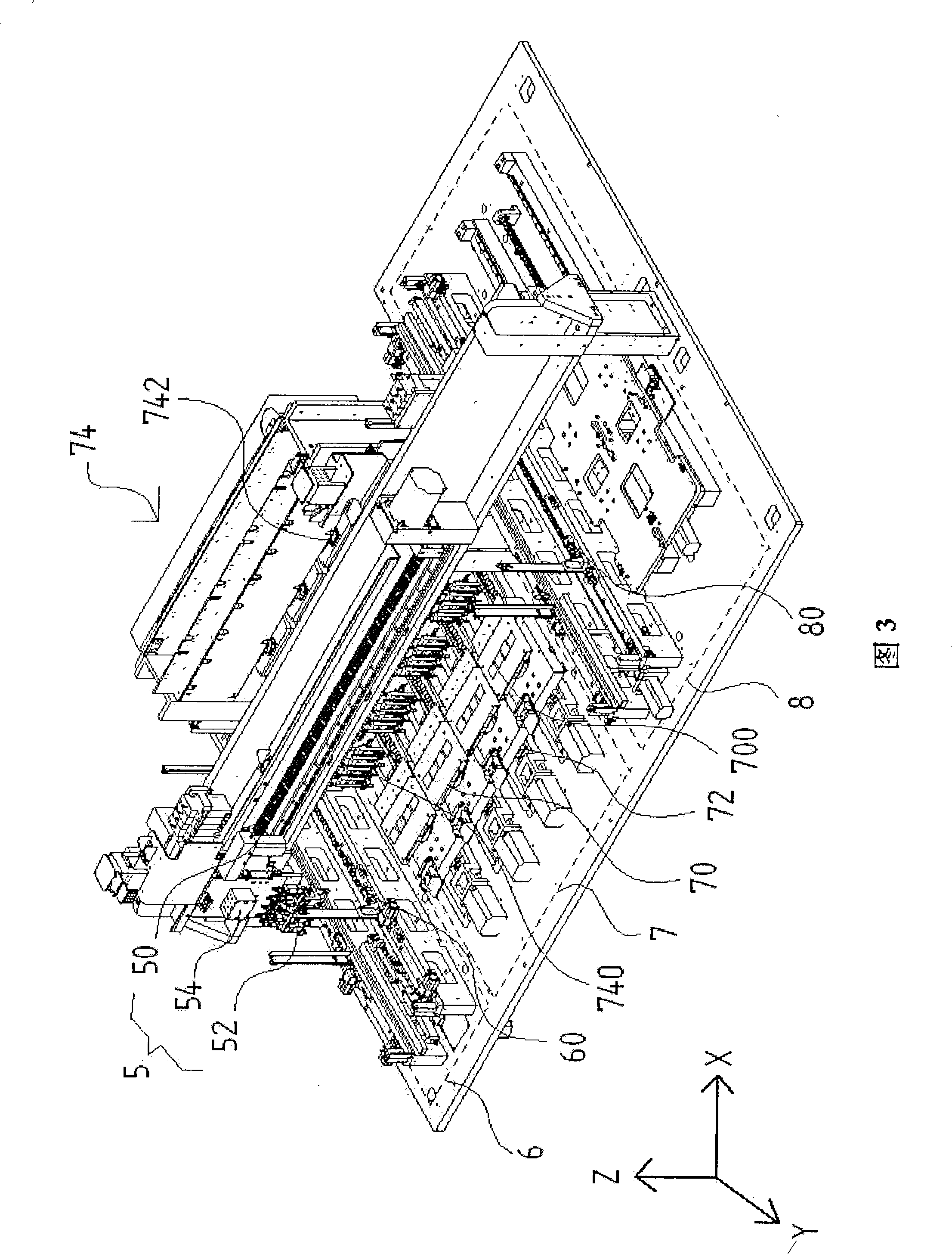
[0053] As shown in FIGS. 3 to 8 , the machine is mainly divided into a feeding area 6 , a testing area 7 and a discharging area 8 . Wherein, the feed area 6 is provided with a feed screw 60; the test area 7 includes a plurality of test bases 70 respectively forming a plurality of accommodating grooves 700, a plurality of driving devices 72 and a test device 74 respectively corresponding to the test bases 70 , Leveling sensor 740 and leveling value display 76; , wherein the discharge area 8 includes a discharge screw 80; carrying the mobile device 5 and the pick...


PUM


Abstract

The invention discloses a detection method comprising the steps as follows: a charging zone, a testing zone and a discharging zone are arranged along a first direction; a bearing mobile device and a pick-up device are mutually opposite and configured along a second direction, and oppositely move in the three zone along the first direction; the components to be tested of the charging zone is sucked by the bearing mobile device through the staggered trend design of the bearing mobile device and the pick-up device; the components to be tested are moved to testing seats of a testing zone; and after each testing seat is driven to pass through units such as a flat testing unit, an electrical testing unit, an efficiency testing unit, etc. by a driving device, the tested component is moved to the discharging bearing disk of the discharging zone by the pick-up device to be positioned. Therefore, the massive detection of the batch is performed, the charging and the discharging is respectively arranged at both ends of the testing zone, so that the machine configuration is integrated, the carrying efficiency and the testing efficiency are improved, the moving frequency of objects to be tested is further reduced, and the yield rate is prevented from reduction due to pointless deterioration.

Description

【Technical field】 [0001] The invention relates to a testing machine, in particular to a multi-test seat testing machine with sequentially arranged feeding areas, testing areas and discharging areas. 【Background technique】 [0002] Regardless of semiconductor components or optical sensing components, before they leave the factory or go online, they must go through layers of inspections to confirm the quality of the components. [0003] As shown in Figure 1, Taiwan's new patent No. 551500, titled "Conveying device for IC testing machine", discloses an automatic testing machine 1, and its machine 1 is provided with a plurality of testing devices 10, each testing device 10 A single test pedestal 100 is formed on each of them. When the carrier tray 121 carrying the IC to be tested is placed in the feeding area 12, the left cantilever pick-and-place device 13 will move to the top of the carrier tray 121, and the suction nozzle 130 will be driven to pick up the IC to be tested. co...

Claims


Application Information

Patent Timeline
IPC IPC(8): G01R31/02G01R31/26G01R1/02
Inventor 陈建名
Owner CHROMA ATE
Why Eureka
Try Eureka