
Electromagnetic repulsion force system and permanent magnetic system coupled self-adapting control mechanism

A technology of electromagnetic repulsion and permanent magnet mechanism, applied in circuits, electrical switches, electrical components, etc., can solve problems such as unfavorable rapid operation of operating mechanisms, unfavorable service life of circuit breakers, and increased mass of eddy current discs, and reduce mechanical strength. requirements, reducing mass, avoiding the effect of high-speed motion

Inactive Publication Date: 2008-12-03
XI AN JIAOTONG UNIV
View PDF0 Cites 53 Cited by
  • Summary
  • Abstract
  • Description
  • Claims
  • Application Information

AI Technical Summary

Problems solved by technology

[0008] The electromagnetic repulsion device used in the above-mentioned quick operating mechanism adopts a round pie-shaped eddy current disk. When the load that the quick operating mechanism needs to drive is large, the electromagnetic repulsion device needs to provide a very large electromagnetic repulsion to achieve faster action. At this time, in order to improve the mechanical strength of the eddy current disk of the electromagnetic repulsion mechanism, it is necessary to increase the thickness of the eddy current disk, which will lead to a substantial increase in the mass of the vortex disk, and the motion inertia of the motion system of the operating mechanism will increase significantly, which is not conducive to the operating mechanism. Perform quick operation under heavy load; at the same time, the above-mentioned quick operating mechanism only provides the only opening action scheme, that is, the electromagnetic repulsion device is used to realize quick action opening. When the operating mechanism performs short-circuit opening of the circuit breaker, Quick action is very necessary, but in the process of using the circuit breaker, short-circuit opening is not common, while opening under rated current and no-load is more frequent, frequent high-speed action will affect the strength of all aspects of the circuit breaker High requirements are put forward, which is not conducive to ensuring a long service life of the circuit breaker

Method used


Image

  • Electromagnetic repulsion force system and permanent magnetic system coupled self-adapting control mechanism
  • Electromagnetic repulsion force system and permanent magnetic system coupled self-adapting control mechanism

Examples


Embodiment Construction

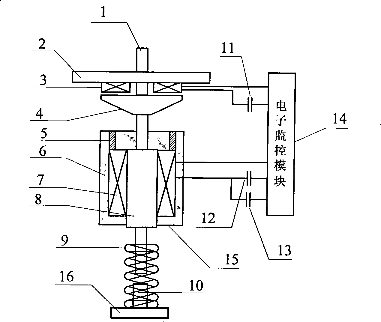
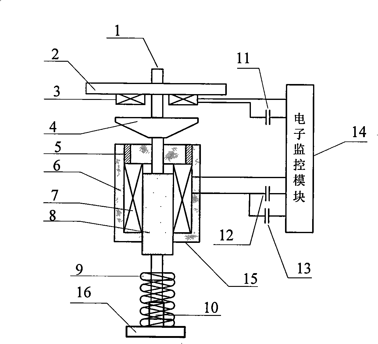
[0019] see figure 1 , figure 2 As shown, the present invention is mainly composed of an electromagnetic repulsion device and a monostable permanent magnet mechanism connected through an axially movable drive rod.

[0020] The electromagnetic repulsion device has the electromagnetic repulsion device metal eddy current disc 4 and the electromagnetic repulsion device coil mounting plate 2 fixedly arranged on the driving rod 1, and the electromagnetic repulsion device coil mounting plate 2 can be fixed on the applied coil of the present invention. On the breaker frame, the electronic monitoring module 14 controls the coil power supply capacitor 11 of the electromagnetic repulsion device to supply power to the coil 3 of the electromagnetic repulsion device.

[0021] The monostable permanent magnet mechanism has the monostable permanent magnet mechanism moving iron core 8 fixedly arranged on the drive rod, the monostable permanent magnet mechanism static iron core 6 fixed on the a...


PUM


Abstract

The invention discloses a self-adaptive control mechanism which couples an electromagnetic repulsion system with a permanent magnetism system. The invention adopts an electromagnetic repulsion device spinning disk of circular table structure, relatively to the circular disk spinning disk, which maintains the mechanical strength and output capacity of the spinning disk, simultaneously greatly reduces the increase of kinematic scheme mass of the control mechanism, and greatly enhances the driving load capacity of the control mechanism. The control mechanism of the invention adopts the self-adaptive motion proposal, which avoids the frequent high speed motion of a breaker, reduces the mechanical strength request for the breaker, and prolongs the motion life of the breaker effectively.

Description

technical field [0001] The invention belongs to an operating mechanism used in a power system circuit breaker, in particular to an adaptive operating mechanism coupled with an electromagnetic repulsion system and a permanent magnet system. Background technique [0002] At present, the operating mechanisms of vacuum circuit breakers mainly include electromagnetic operating mechanisms, spring operating mechanisms and permanent magnetic operating mechanisms. [0003] The electromagnetic operating mechanism has been widely used in the early stage of the development of vacuum circuit breakers, but the electromagnetic operating mechanism has a bulky structure and takes a long time to operate. [0004] The spring operating mechanism is the most commonly used type of operating mechanism for vacuum circuit breakers. Its advantage is that it does not require a high-power DC power supply, but only needs a low-power AC-DC dual-purpose energy storage motor. The disadvantage is that the s...

Claims


Application Information

Patent Timeline
IPC IPC(8): H01H3/28H01H33/666H01H33/38
Inventor 史宗谦贾申利王立军朱天胜宋晓川
Owner XI AN JIAOTONG UNIV
Learn More