MIMO mobile terminal multi-antenna with high isolation and low correlated characteristic

A mobile terminal, low-correlation technology, applied in the field of planar four-element antennas for mobile terminals, to achieve the effects of easy fabrication, improved isolation characteristics, and increased channel capacity

Inactive Publication Date: 2008-12-03
HARBIN INST OF TECH
View PDF0 Cites 35 Cited by
  • Summary
  • Abstract
  • Description
  • Claims
  • Application Information

AI Technical Summary

Problems solved by technology

[0003] In order to solve the problem of integrating multiple antennas in a relatively small space, the present

Method used


Image

  • MIMO mobile terminal multi-antenna with high isolation and low correlated characteristic
  • MIMO mobile terminal multi-antenna with high isolation and low correlated characteristic
  • MIMO mobile terminal multi-antenna with high isolation and low correlated characteristic

Examples


specific Embodiment approach 1

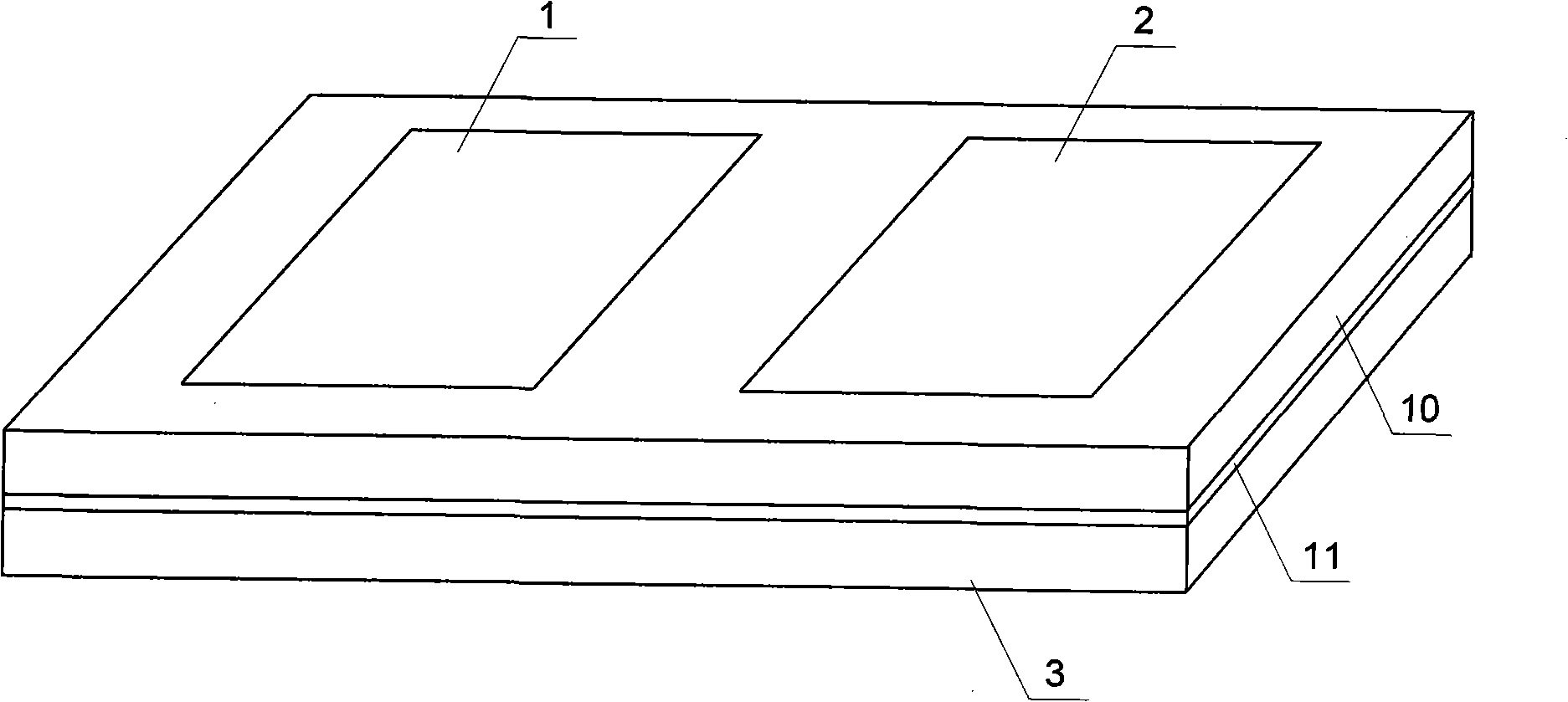
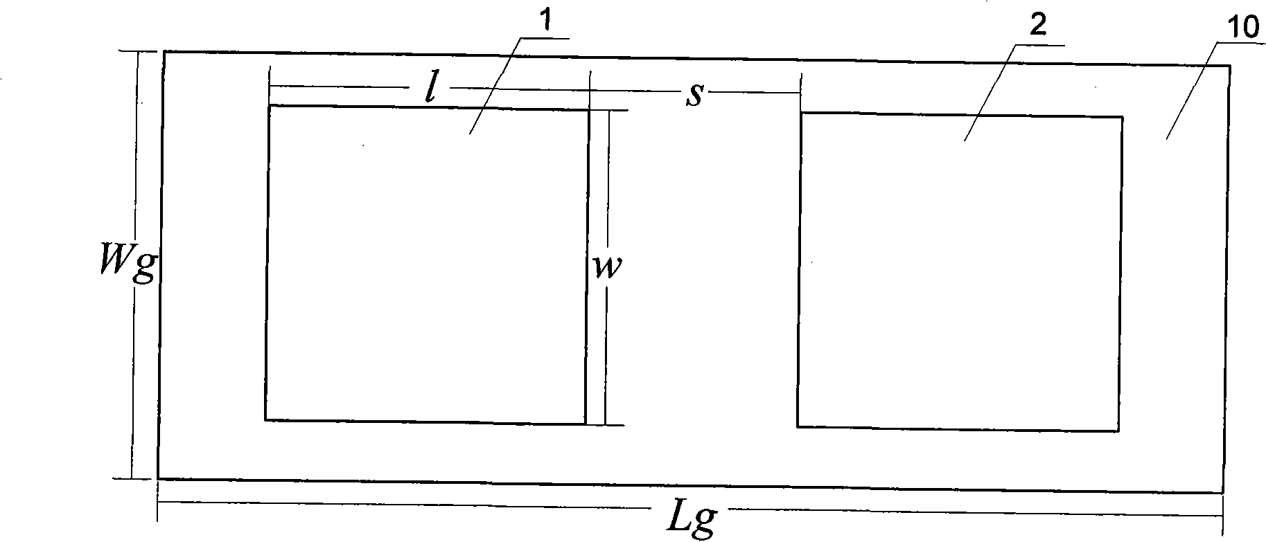
[0008] Specific implementation mode one: combine Figures 1 to 6 Describe this embodiment, this embodiment consists of the first patch 1, the second patch 2, the first feeding microstrip line 4, the second feeding microstrip line 5, the third feeding microstrip line 6, the fourth feeding microstrip line The feeding microstrip line 7, the antenna main body and the lower floor 3 are composed; the antenna main body is a double-layer dielectric structure, and the antenna main body is composed of an upper layer medium 10 and an intermediate medium 11, and the upper surface of the antenna main body is attached with shapes and sizes The same first patch 1 and second patch 2, the lower surface of the antenna main body is provided with a lower floor 3, and the center of the lower floor 3 is provided with a dumbbell-shaped opening 9; the first feeder microstrip line 4 and the second feeder The electric microstrip line 5 is the first feeding microstrip line group, the third feeding micro...

specific Embodiment approach 2

[0009] Specific implementation mode two: combination Figure 5 and Figure 6 This embodiment is described. The difference between this embodiment and the first embodiment is that both ends of the dumbbell-shaped opening 9 are rectangular or circular. Other compositions and connection methods are the same as those in Embodiment 1. The dumbbell-shaped opening 9 is longitudinally opened between the two patches, which can be equivalent to an LC resonant circuit, which improves the isolation characteristics between the antennas, reduces the correlation, and increases the channel capacity of the system.

specific Embodiment approach 3

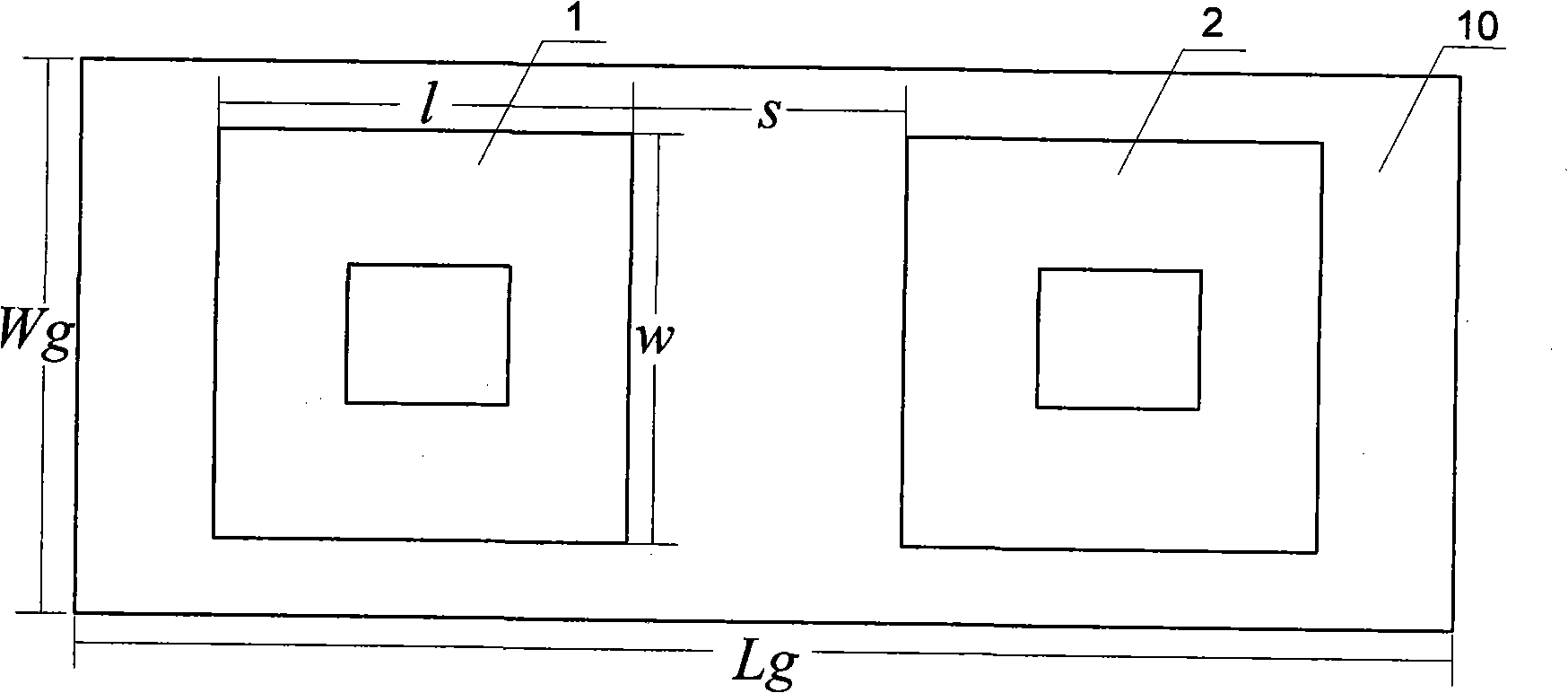
[0010] Specific implementation mode three: combination image 3 This embodiment is described. The difference between this embodiment and the first embodiment is that the first patch 1 and the second patch 2 are rectangular or "back". Other compositions and connection methods are the same as those in Embodiment 1. The "back" shape of the first patch 1 and the second patch 2 is used to reduce the amount of patches, obtain better impedance matching characteristics, and widen the bandwidth.


PUM

PropertyMeasurementUnit
Widthaaaaaaaaaa
Lengthaaaaaaaaaa
Widthaaaaaaaaaa

Abstract

The invention provides an MIMO mobile terminal multi-antenna with high separation and low corresponding characteristic. The invention relates to the field of wireless communication and solves the problem that a plurality of antennas are integrated in small spaces. The antenna main body of the invention is a dual-layer medium structure, namely an upper-layer medium and a middle medium; a first patch and a second patch with identical shape and size are attached to the left side and the right side of the upper surface of the dual-layer medium structure intermittently; the lower surface of the dual-layer medium structure is provided with a lower floor; the center of the lower floor is provided with a dumbbell-shaped opening; a first feeding microstrip line and a second feeding microstrip line are the first feeding microstrip line group; other two feeding microstrip lines are the second feeding microstrip line group; two feeding microstrip line groups are arranged between the upper-layer medium and a middle medium and respectively arranged at one side of the first patch and the second patch; the feeding micro-strip lines inside each feeding micro-strip line group are vertical to each other, not crossed to each other and mutually symmetrical on the structure. The MIMO mobile terminal multi-antenna improves the separation characteristic between the antennas, reduces the correlation, has the advantages of compact structure, easy integration, small space occupying, and can be used for the MIMO mobile terminal and low cost.

Description

technical field [0001] The invention relates to the technical field of wireless communication, in particular to a mobile terminal planar four-element antenna applied to a super 3G / 4G mobile communication terminal multi-input multi-output (multi-input multi-output, MIMO) system. Background technique [0002] The MIMO technology in mobile communication refers to the technology that uses multiple transmitting antennas and multiple receiving antennas for wireless transmission. The wireless communication system using this technology is the MIMO system. When the antennas are far enough away from each other, the signal transmission between each transmitting antenna and each receiving antenna can be regarded as independent of each other, and the multiple antennas used can be called discrete multi-antennas, such as applied to space This is the case for multiple antennas with diversity. If the antennas are very close to each other, the signal transmission from each transmitting anten...

Claims


Application Information

Patent Timeline
IPC IPC(8): H01Q21/28H01Q1/38H01Q13/08
Inventor 宋朝晖丁志勇张乘风刘美佳
Owner HARBIN INST OF TECH
Why Eureka
Try Eureka