Optical module and method of producing optical module

An optical module and manufacturing method technology, applied in the coupling of optics, optical components, optical waveguides, etc., can solve problems such as operability, impact resistance, mechanical reliability, fiber breakage, etc., to avoid fiber breakage and simplify Manufacturing process, the effect of improving operability

Inactive Publication Date: 2008-12-03
MITSUMI ELECTRIC CO LTD
View PDF1 Cites 3 Cited by
  • Summary
  • Abstract
  • Description
  • Claims
  • Application Information

AI Technical Summary

Problems solved by technology

[0007] However, if Figure 6B As shown, in the existing optical module 31, since the uncovered optical fibers 35a, 35b are in contact with the ends 36 of the V-grooves 323a, 323b, the parts where the optical fibers 35a, 35b are fixed on the subst

Method used


Image

  • Optical module and method of producing optical module
  • Optical module and method of producing optical module
  • Optical module and method of producing optical module

Examples


Embodiment Construction

[0038] The first embodiment will be described.

[0039] First, the optical module 1 according to the first embodiment of the present invention will be described.

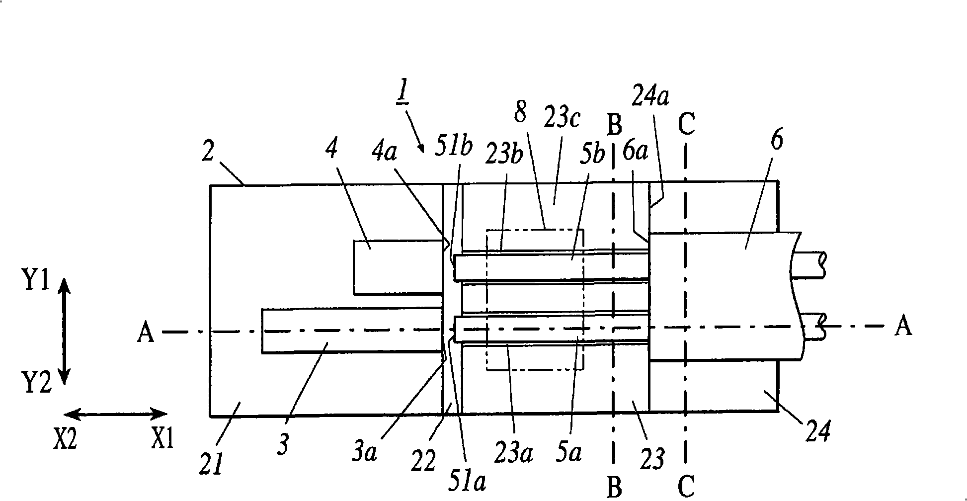
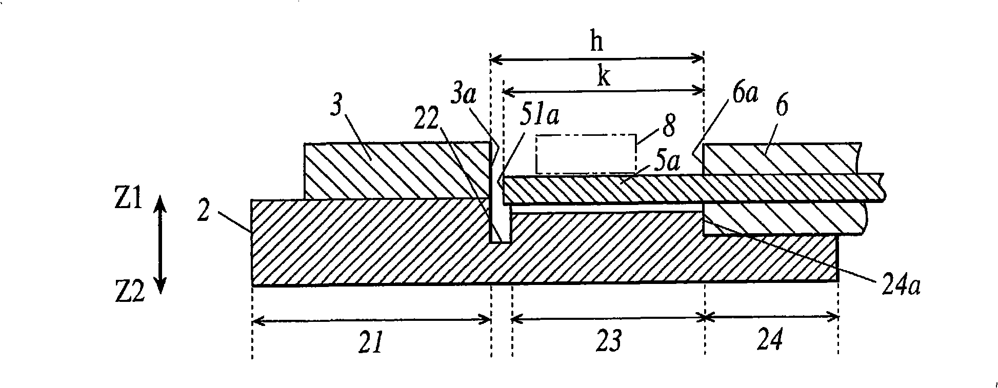
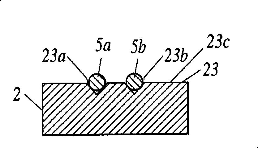
[0040] Figure 1A is a plan view showing the optical module 1 of the first embodiment, Figure 1B yes Figure 1A The A-A line sectional view, Figure 1C yes Figure 1A The end view of the B-B line, Figure 1D yes Figure 1A The end view of the C-C line.

[0041] Such as Figure 1A As shown, the optical module 1 is configured by mounting PD3, LD4, and optical fibers 5a, 5b on a substrate 2. The optical fibers 5a, 5b are covered by the covering part 6, and are partially exposed. The exposed portions of the optical fibers 5a, 5b are fixed with a cover glass 8 from above.

[0042] The substrate 2 is a plate-shaped substrate formed of single crystal silicon (Si), and as Figure 1A and Figure 1B As shown, it is composed of an optical component placement part 21 , a groove part 22 , a V-groove forming part 23 ...


PUM


Abstract

An optical module where breaking of an optical fiber is avoided to improve ease of handling in the assembly process of the module and mechanical reliability of the module including resistance to impact. The optical module has a PD (3) and an optical fire (5a) that are mounted on the same substrate (2). A covering section (6) for covering the optical fiber (5a) is placed on a deep trench section (24) having a predetermined depth in the Z2 direction from a V-groove-formed surface where a V-groove for mounting the optical fiber (5a) is formed. The distance h from an end face (3a) of the PD (3) to an end face (24a) of the deep trench section (24) and the distance k from an end face (51a) of the optical fiber (5a) to an end face (6a) of the covering section (6) satisfy the relationship of h>k. The optical fiber (5a) is mounted with both the end face (6a) of the covering section (6) and the end face (24a) of the deep trench section (24) made to be in contact with each other.

Description

technical field [0001] The invention relates to an optical module in which an optical fiber and an optical component are integrally integrated on a substrate and a manufacturing method of the optical module. Background technique [0002] In recent years, with the increase in speed of data communication, instead of communication using metal cables, optical communication enabling broadband communication with low loss has become popular. For optical communication, positioning when connecting cables is important, for example, forming a V-shaped groove (hereinafter referred to as V-groove) on the substrate, and fixing the optical fiber in this V-groove, thereby positioning the optical fiber (For example, refer to Patent Document 1). [0003] In addition, optical axis alignment using V-grooves for optical fiber mounting is also performed for optical modules in which optical fibers and various optical components are integrally integrated on a substrate. Optical components refer t...

Claims


Application Information

Patent Timeline
IPC IPC(8): G02B6/42
CPCG02B6/3692G02B6/3652G02B6/3636G02B6/423
Inventor 中村明
Owner MITSUMI ELECTRIC CO LTD
Why Eureka
Try Eureka