
Nanofiber filter facemasks and cabin filters

A nanofiber and microfiber technology, applied in membrane filters, filtration separation, dispersed particle filtration, etc., can solve the problems of undurable and uneconomical filters

Inactive Publication Date: 2008-12-10
THE HONG KONG POLYTECHNIC UNIV
View PDF0 Cites 43 Cited by
  • Summary
  • Abstract
  • Description
  • Claims
  • Application Information

AI Technical Summary

Problems solved by technology

The filter media is generally ineffective at filtering submicron (ultramicron) particles and can easily become loaded with accumulated particles that restrict fluid flow
They are also generally uneconomical as they need to be replaced very frequently
Furthermore, even if the filter media has a dense pore size, as in the case of filter media using non-woven (non-woven) micron-sized fibers, such as HEPA filters (high-efficiency performance air filters), there may still be significant drawbacks
These filters tend to be less durable

Method used


Image

  • Nanofiber filter facemasks and cabin filters
  • Nanofiber filter facemasks and cabin filters
  • Nanofiber filter facemasks and cabin filters

Examples


example 1

[0063] Example 1: Method and conditions of electrospinning process for producing nanofibers

[0064] Pellets of Nylon 6 were added to 98% formic acid in appropriate proportions (i.e., 15, 18, 21 and 24 wt% N6 to 98% formic acid) and placed in an electrospinning machine (available from KES Teng Technology Co., Ltd. (Japan) obtained from NEU-010 nanofibers) for mixing. The machine has an electrode voltage of 25 kV, a tip-to-collector distance of 14 cm, and a 0.72 mm 3 / s to 1.45mm 3 / s jet feed rate. After the polymer mixture was collected from the machine, it was allowed to stand at room temperature overnight or until a honey-like viscous liquid formed. Optionally, an ultrasonic generator can be used to mix the polymer suspension and solvent.

example 2

[0065] Example 2: Method of Meltblown Process for Producing Nanofibers

[0066]Melt blowing (MB) technology is used to produce nanofibers directly from polymers or resins using high velocity air flow or other suitable forces. The MB process uses five elements: extruder, metering pump, die assembly, web forming and winding. The extruder consists of a heated barrel with a rotating screw inside to melt the polymer and pump it into the die assembly. The die assembly has a die nozzle (nose), which is a wide, hollow metal cone with several hundred holes along its width. The polymer melt is extruded through the orifices to form filament bundles which are then attenuated by high velocity hot air and exit the top and bottom sides of the die nozzle to form fine fibers. High-velocity hot air is generated by an air compressor and passed through a heat exchange device. Typical gas temperatures range from 230°C to 360°C at velocities of 0.5 to 0.8 times the speed of sound. Then, the n...


PUM

PropertyMeasurementUnit
The average diameteraaaaaaaaaa
Thicknessaaaaaaaaaa
The average diameteraaaaaaaaaa

Abstract

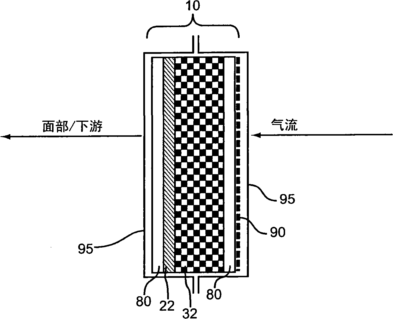
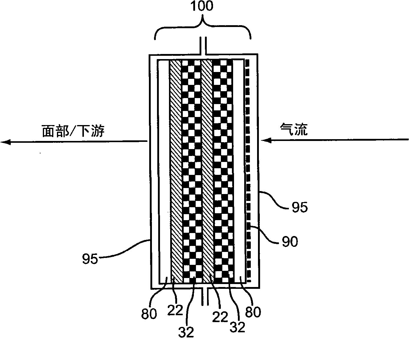
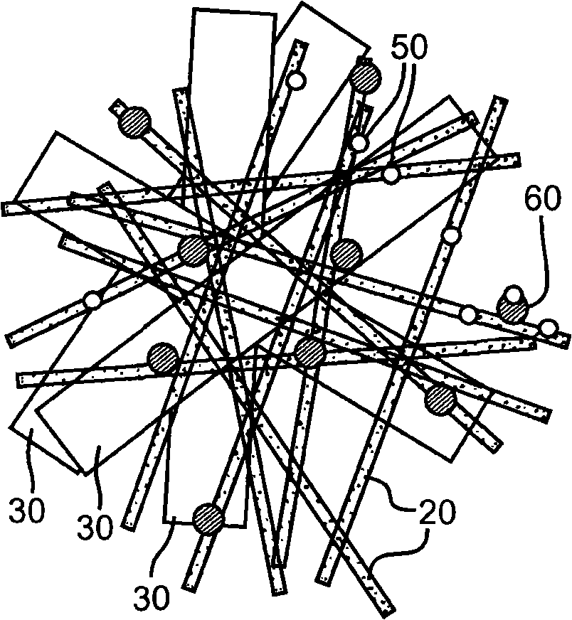
The invention relates to a nanofiber filter veil and cabinet filter, in particular to a filtration medium including a fine filter layer having a plurality of nanofibers and a coarse filter layer having a plurality of microfibers attached to the fine filter layer. The coarse filter layer is positioned proximal to a direction of fluid flow, and the fine filter layer is positioned distal to the direction of fluid flow.

Description

[0001] This application claims priority to U.S. non-provisional application Serial No. 11 / 740,513, filed April 26, 2007, entitled "Nanofiber Filtration Face Masks and Cabin Filters," which is incorporated by reference in its entirety this. technical field [0002] The present invention relates to nanofiber filtering masks and cabin filters, and more particularly to a filter medium and a method of making the filter medium. Background technique [0003] Airflows often carry particulate matter including heavy metals, toxic organic chemicals, and selected microbial molecules such as viruses. Conventional filter media include layered materials containing fibers of substances such as glass fibers, metals, ceramics, and polymeric components. Such filter media are generally ineffective at filtering submicron (ultramicron) particles and may easily become loaded with accumulated particles that restrict fluid flow. They are also generally not economical because they need to be replac...

Claims


Application Information

Patent Timeline
IPC IPC(8): B01D39/04B01D46/30
CPCB01D39/1623B01D46/0028B01D46/0036B01D46/10B01D2239/025B01D2239/0258B01D2239/0442B01D2239/065B01D2275/10Y10T29/49801
Inventor 梁焕方
Owner THE HONG KONG POLYTECHNIC UNIV
Learn More