Phase-change adsorption air dehumidifier

An air dehumidification and phase change technology, applied in combustible gas purification, combustible gas purification/transformation, filter regeneration, etc., can solve the problem of reducing the water vapor potential difference between the adsorbent and air, low dehumidification effect, and increased outlet temperature, etc. problem, achieve the effect of improving dehumidification effect, improving dehumidification efficiency and preventing overheating

Inactive Publication Date: 2008-12-10
ZHEJIANG SCI-TECH UNIV
View PDF0 Cites 7 Cited by
  • Summary
  • Abstract
  • Description
  • Claims
  • Application Information

AI Technical Summary

Problems solved by technology

When working continuously, switch operation between two beds is adopted, one bed is regenerated and the other bed is dehumidified; the disadvantage is that the system accumulates a large amount of heat energy during regeneration, and after switching to dehumidification mode, most of the accumulated heat will be borne by the treated air. The outlet temperature increases significantly, which increases the processing burden of subsequent links
When working as a gap, the adsorbent needs to be replaced frequently and regenerated separately, and because there is no internal cooling, the adsorption heat generated during the adsorption process will gradually increase the bed temperature, thereby reducing the water vapor between the adsorbent and the air. Poor momentum will eventually affect the dehumidification effect
It can be seen that the high outlet temperature of the treated air and the low dehumidification effect are the two main disadvantages of the adiabatic fixed adsorption bed.

Method used


Image

  • Phase-change adsorption air dehumidifier
  • Phase-change adsorption air dehumidifier

Examples


Embodiment Construction

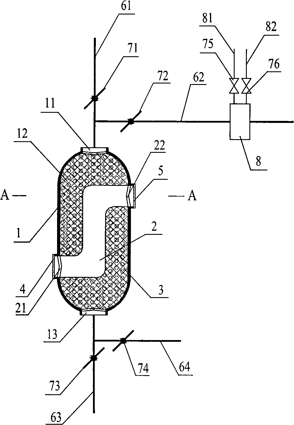
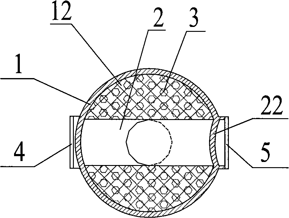
[0021] figure 1 with figure 2 In combination, a phase change adsorption air dehumidification device is provided, which includes a phase change adsorption reactor 1 with a cavity 12 inside, and the top opening 11 and the bottom opening 13 of the phase change adsorption reactor 1 are in communication with the cavity 12 . The processed air outlet pipe 61 is sealed and connected with the top opening 11, and a cut-off valve I71 is provided on the processed air outlet pipe 61. One end of the regeneration air inlet pipe 62 is sealed and connected with the top opening 11, and the other end is connected with the regeneration air heater 8, and a shut-off valve II 72 is provided on the regeneration air inlet pipe 62; The heat medium inlet pipe 81 and the heat medium outlet pipe 82, in order to save energy, the regenerative air heater 8 selects the heater provided by the solar heat collection system; the heat medium inlet pipe 81 is provided with a stop valve V75, Outlet pipe 82 is pro...


PUM


Abstract

The invention disclose a phase-transition absorption air dehumidifying device, which comprises consists a phase-transition reactor (1) in which a cavity (12) is arranged; wherein, a top opening (11) and a bottom opening (13) of the phase-transition reactor (1) are both communicated with the cavity (12); the top opening (11) is separately connected with an outlet pipe for processed air (61) and an inlet pipe for regenerated air (62) in a sealed way; the bottom opening (13) is separately connected with an inlet pipe for processed air (63) and an outlet pipe (64) for regenerated air in a sealed way; the other end of the inlet pipe for regenerated air (62) is connected with a heater for regenerated air (8); an inlet manifold for heat medium (81) and an outlet manifold for heat medium (82) are respectively arranged on the heater for regenerated air (8); an inner-cooling ventilation pipeline (2) is arranged in the cavity (12). The application of the device of the invention to the dehumidification provides good dehumidification effect, and can ensure that the temperature at the outlet for processed air is low.

Description

technical field [0001] The invention relates to an air dehumidification device, in particular to a phase change adsorption air dehumidification device. Background technique [0002] Air temperature and humidity are two important parameters that need to be controlled in the air conditioning process. Dehumidification energy consumption accounts for 20%-40% of the energy consumption of the air conditioning system; the traditional cooling and dehumidification method has low water supply temperature, low cooling efficiency, and low air temperature after dehumidification , In order to reach the air supply state point, reheating is required, resulting in serious irreversible losses. Therefore, people have developed the temperature and humidity separation control technology, that is, the water vapor in the air is removed by a special dehumidification system, and the air conditioning system is only responsible for the sensible heat of the air. Generally, this type of dehumidificatio...

Claims


Application Information

Patent Timeline
Patent Type & Authority Applications(China)
IPC IPC(8): B01D53/26B01D53/04B01J20/34
Inventor 王厉骆菁菁
Owner ZHEJIANG SCI-TECH UNIV
Why Eureka
Try Eureka