Yarn guiding mechanism on textile machines

A technology of reciprocating motion and textile machine, which is used in transportation and packaging, transportation of filamentous materials, thin material processing, etc., can solve the problems of inability to adjust the lifting stroke of the reciprocating rod, vibration, and short service life.

Inactive Publication Date: 2008-12-10
RIETER CZ AS
View PDF0 Cites 0 Cited by
  • Summary
  • Abstract
  • Description
  • Claims
  • Application Information

AI Technical Summary

Problems solved by technology

These springs cause shock and vibration to this reciprocating rod and they also have a short lifespan
[0012] In addition, most of these devices cannot adjust the lifting stroke of the reciprocating rod and thereby change the width of the package on the bobbin
The reciprocating rod is often subjected to enormous pressures, requiring a corresponding increase in cross-section, which in turn leads to an increase in the weight of the distributing rod, which in turn increases the undesired inertial forces

Method used


Image

  • Yarn guiding mechanism on textile machines
  • Yarn guiding mechanism on textile machines
  • Yarn guiding mechanism on textile machines

Examples


Embodiment Construction

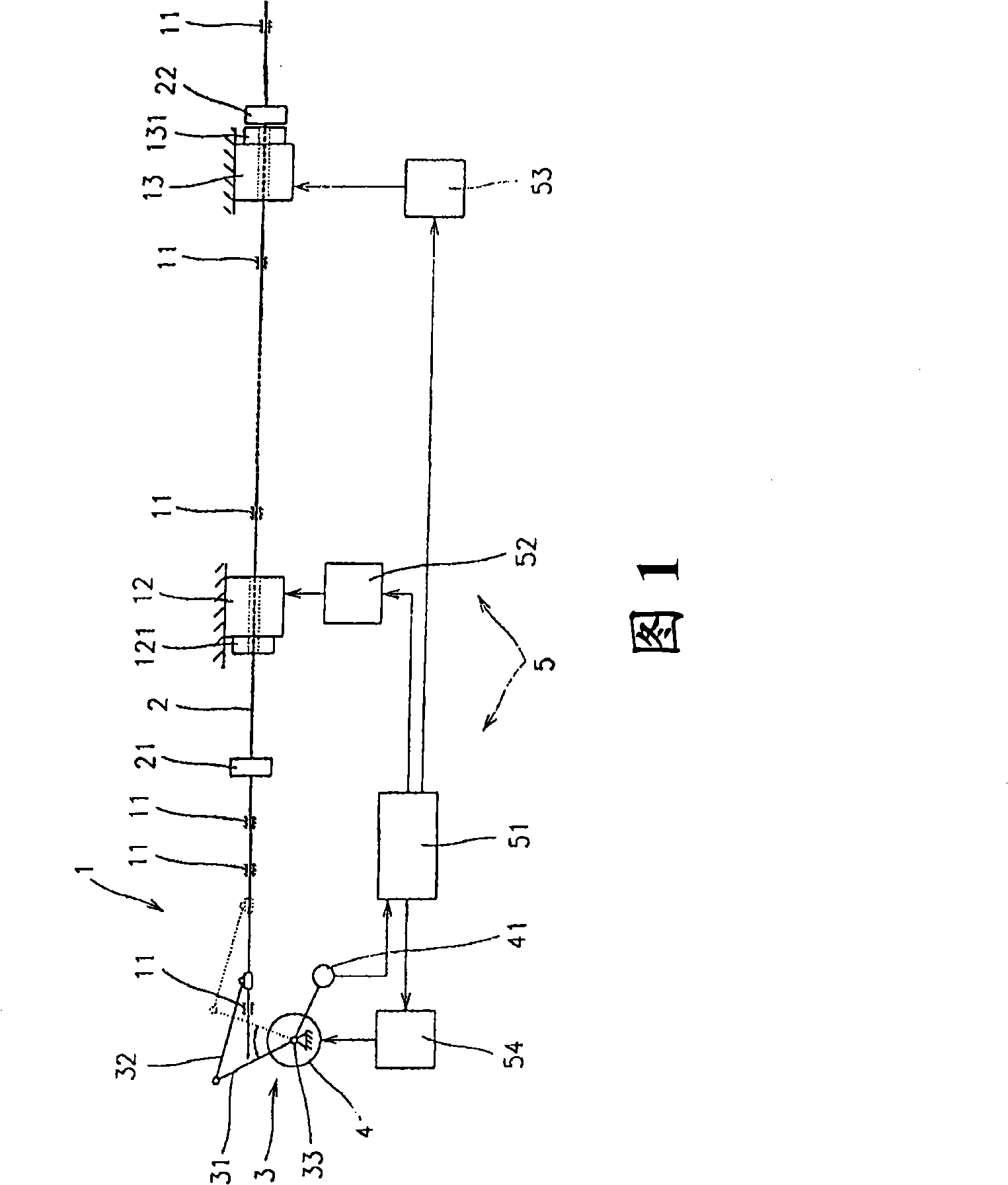
[0063] A basic embodiment of the device according to the invention is shown in FIG. 1 . On the frame 1 of the textile machine, a reciprocating rod 2 is installed via a guide device 11 . The reciprocating rod 2 is driven by an eccentric crank mechanism 3 comprising a crank 31 and a connecting rod 32 . The crankshaft 33 is concentrically connected to the output of the drive servo motor 4 equipped with a position sensor 41 . Moving magnets 21 and 22 are fixedly connected to the reciprocating rod 2 . On the frame 1 of the machine are connected linear servomotors 12, 13, with static magnets 121 and 131 connected to their outputs. The reciprocating rod 2 freely passes through the openings on the static magnets 121, 131 and the linear servo motors 12, 13 (possibly on the outside of the linear servo motors 12, 13). The moving magnet 21 and the static magnet 121 form a co-operating couple like the moving magnet 22 and the static magnet 131 . The magnets are mutually distributed (mu...


PUM


Abstract

The present invention discloses a yarn reciprocating movement device for a spinner, particularly discloses a device used for reciprocating movement of yarn. Yarn is winded on a bobbin which is installed in the winding mechanism of an operating unit of the spinner. The device of the invention comprises a vertical reciprocating rod (2) shared by a row of operating units, the vertical reciprocating rod (2) is connected with a driving mechanism generating straight-line reverse movement and also is connected with a control system (5) which locates the die point route of the vertical reciprocating rod (2); simultaneously, the vertical reciprocating rod (2) is parallel to the winding shaft of a row of operating units. At the same time, two pairs of magnets (21,121; 22,131) are mutually arranged on the reciprocating rod (2) and the machine frame (1) at intervals, wherein each pair of magnets include a static magnet (121,131) and a moving magnet (21, 22), and the magnets are installed in such a way that magnets having the same polarity are arranged relative to each other. The static magnet is arranged on the machine frame, and the moving magnet is arranged on the reciprocating rod.

Description

technical field [0001] A device for reciprocating yarn (yarn traversing), the yarn is wound on a bobbin installed in the winding mechanism of the operating unit of the textile machine, the device includes: a longitudinal reciprocating rod shared by a row of operating units, the reciprocating The rod is coupled to a drive that produces a linear reverse motion, and to a control system that defines the course of the up and down travel of the reciprocating rod, while the longitudinal reciprocating rod is parallel to the longitudinal winding axis assigned to a row of operating units. Background technique [0002] Yarn reciprocation during bobbin winding of a textile machine such as an air spinning machine, winding machine or two-for-one twisting machine is usually performed by means of a continuous reciprocating rod advancing along one side of the machine operating unit. In the case of a large number of operating units arranged in a row, the reciprocating rods are, for example, 3...

Claims


Application Information

Patent Timeline
Patent Type & Authority Applications(China)
IPC IPC(8): B65H54/28B65H54/74
Inventor P·西德洛夫P·斯科普F·福恩
Owner RIETER CZ AS
Why Eureka
Try Eureka