Tele-metering direct-reading encoder of meter counter
A counter and direct reading technology, applied in the field of counter remote transmission and direct reading encoder, can solve the problems of high process requirements, failure, unstable character wheel code reading, etc., to reduce assembly process requirements, stable and accurate reading judgment, Stable and accurate readings
- Summary
- Abstract
- Description
- Claims
- Application Information
AI Technical Summary
Problems solved by technology
Method used
Image
Examples
Embodiment 1
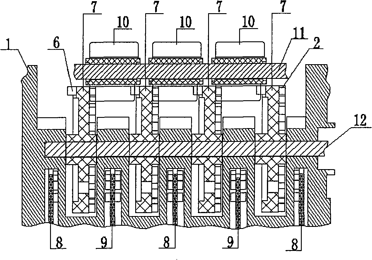
[0029] Example 1: from figure 1 It can be clearly seen that the remote transmission direct-reading encoder of the meter counter is composed of a transparent character wheel box 1, a number of opaque coded character wheels 7, a character wheel shaft 12, a carry coupling wheel 10, a carry coupling wheel shaft 11, a transmission line circuit board 8, a receiving The pipeline circuit board 9 is composed of several encoding character wheels 7 arranged at intervals through the character wheel shafts 12 and installed in the transparent character wheel box 1. Axle 11 is installed in the transparent word wheel box 1 outside code word wheel 7 circumferences.
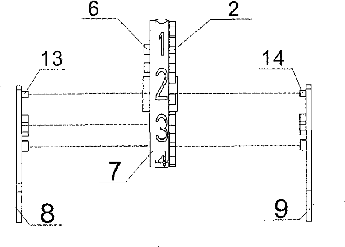
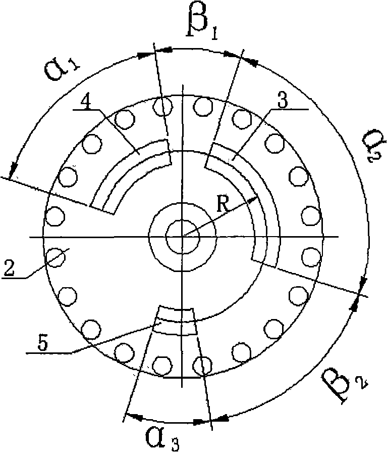
[0030] 20 carry driven teeth 2 are evenly distributed on one side of the said coding word wheel 7, and 2 carry active teeth 6 are arranged on the appropriate position on the other side of the ring surface (see figure 2 ); the wheel spoke equal radius R concentric circle of coding character wheel 7 is all provided with the first ...
Embodiment 2
[0034] Embodiment 2: The example structure of the meter counter remote transmission direct-reading encoder is basically the same as that of Embodiment 1, the only difference is that the first light-transmitting hole groove 3 on the encoding character wheel 7 corresponds to the central angle α 1 27°±2°, the second light-transmitting hole slot 4 corresponds to the central angle α 2 is 90°±2°, the third light-transmitting hole slot 5 corresponds to the central angle α 3 63°±2°; the central angle β between the first light-transmitting hole groove 3 and the second light-transmitting hole groove 4 1 63°±2°, the central angle β between the second light-transmitting hole groove 4 and the third light-transmitting hole groove 5 2 is 27°±2°.
[0035] Its working process is identical with embodiment 1.
Embodiment 3
[0036] Embodiment 3: The example structure of the remote transmission direct-reading encoder of the meter counter is basically the same as that of Embodiment 1, the only difference is that the first light-transmitting hole groove 3 on the encoding character wheel 7 corresponds to the central angle α 1 is 45°±3°, the second light-transmitting hole slot 4 corresponds to the central angle α 2 90°±3°, the third light-transmitting hole slot 5 corresponds to the central angle α 3 45°±3°; the central angle β between the first light-transmitting hole groove 3 and the second light-transmitting hole groove 4 1 45°±3°, the central angle β between the second light-transmitting hole groove 4 and the third light-transmitting hole groove 5 2 is 45°±3°.
[0037] Its working process is identical with embodiment 1.
PUM
 Abstract
Description
Claims
Application Information
 - R&D
- Intellectual Property
- Life Sciences
- Materials
- Tech Scout
- Unparalleled Data Quality
- Higher Quality Content
- 60% Fewer Hallucinations
Browse by: Latest US Patents, China's latest patents, Technical Efficacy Thesaurus, Application Domain, Technology Topic, Popular Technical Reports.
© 2025 PatSnap. All rights reserved.Legal|Privacy policy|Modern Slavery Act Transparency Statement|Sitemap|About US| Contact US: help@patsnap.com


