LCD display panel
A liquid crystal display and panel technology, which is applied in the direction of instruments, nonlinear optics, optics, etc., can solve problems such as poor picture quality, uneven thickness of the LCD screen box, liquid crystal pollution, etc., to improve the display effect, ensure the uniformity of the box thickness, The effect of ensuring the uniformity of liquid crystal
- Summary
- Abstract
- Description
- Claims
- Application Information
AI Technical Summary
Problems solved by technology
Method used
Image
Examples
Embodiment 1
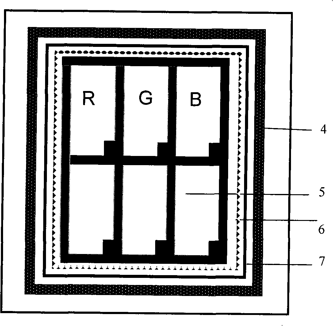
[0035] Figure 5 It is a schematic diagram of the implementation structure of the inner layer isolation frame in the specific embodiment 1 of the present invention. like Figure 5 As shown, in the present embodiment, a series of square grooves 10 of the inner layer isolation frame are formed on the inner layer isolation frame 6, the height of the inner layer isolation frame is H, and the depth of the square groove 10 of the inner layer isolation frame is 2 / 3H Left and right, the distance between the square grooves 10 of the inner layer isolating frame is W, and the width of the square groove of the inner layer isolating frame is about 1 / 3W. Image 6 It is a schematic diagram of the structure of the outer isolation frame proposed by the present invention. like Image 6 As shown, the heights of all positions of the outer layer isolation frame 7 are H.
[0036] Figure 7 It is a schematic diagram of the rear panel after adding the isolation frame and dropping the liquid crys...
Embodiment 2
[0039] Figure 9 It is a structural schematic diagram of an embodiment of the inner layer isolation frame in the specific embodiment 2 of the present invention. like Figure 9 As shown, the groove 6 structure of the inner layer isolation frame in this embodiment is different from the square structure in the specific embodiment 1, specifically, a series of inner layer isolation frame triangular grooves 11 are formed on the inner layer isolation frame 6, the The width and depth of the triangular groove 11 of the inner spacer frame can be set with reference to the width and depth in the specific embodiment, and the specific function of the triangular groove 11 of the inner layer spacer frame is the same as in the specific embodiment 1, and will not be described in detail.
Embodiment 3
[0041] Figure 10 It is a schematic diagram of the embodiment structure of the inner layer isolation frame in the specific embodiment 3 of the present invention. like Figure 9 As shown, the groove structure of the inner layer isolation frame in this embodiment is different from the square structure in the specific embodiment 1, specifically, a series of inner layer isolation frame trapezoidal grooves 12 are formed on the inner layer isolation frame 6, the inner layer isolation frame The width and depth of the trapezoidal groove 12 of the layer isolation frame can be set with reference to the width and depth in the specific embodiment, and the specific function of the trapezoidal groove 12 of the inner layer isolation frame is the same as that in the specific embodiment 1, and will not be described in detail.
PUM
 Abstract
Description
Claims
Application Information
 - R&D
- Intellectual Property
- Life Sciences
- Materials
- Tech Scout
- Unparalleled Data Quality
- Higher Quality Content
- 60% Fewer Hallucinations
Browse by: Latest US Patents, China's latest patents, Technical Efficacy Thesaurus, Application Domain, Technology Topic, Popular Technical Reports.
© 2025 PatSnap. All rights reserved.Legal|Privacy policy|Modern Slavery Act Transparency Statement|Sitemap|About US| Contact US: help@patsnap.com


