Transformer and its insulation cover

A transformer and insulating cover technology, applied in the field of transformers, can solve the problems of insufficient distance, inability to effectively isolate, increase the size of the winding frame 11, etc., and achieve the effect of reducing the size

Inactive Publication Date: 2008-12-10
DELTA ELECTRONICS INC
View PDF0 Cites 0 Cited by
  • Summary
  • Abstract
  • Description
  • Claims
  • Application Information

AI Technical Summary

Problems solved by technology

[0003] However, in the prior art, the insulation method of the transformer 1 is only isolated from the iron core group 13 by the upper cover 14, and the two ends of the iron core group 13 are exposed outside the upper cover 14.
In order to avoid insufficient distance between the core set 13 and the pins of the winding wires 121, 122, it is necessary to increase the size of the bobbin 11 so that the distance between the core set 13 and the pins complies with safety regulations. As a result, the size of the transformer 1 cannot be reduced, which does not conform to the design direction of miniaturization
In addition, the design of the upper cover 14 cannot effectively isolate the interference between the core set 13 and other electronic components, let alone meet safety standards

Method used


Image

  • Transformer and its insulation cover
  • Transformer and its insulation cover
  • Transformer and its insulation cover

Examples


Embodiment Construction

[0022] The transformer and its insulating cover of the preferred embodiment of the present invention will be described below with reference to the relevant drawings, wherein the same components will be described with the same reference symbols.

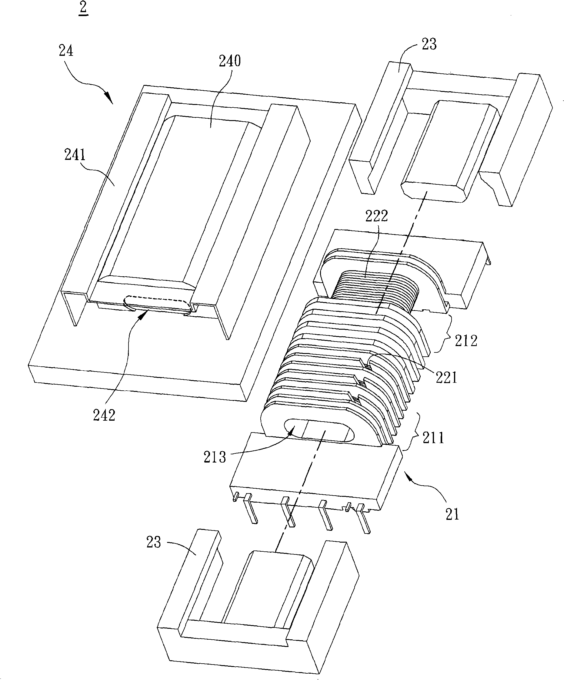
[0023] Please refer to image 3 and Figure 4 As shown, the transformer 2 of the preferred embodiment of the present invention includes a winding frame 21 , two sets of winding wires 221 , 222 , an iron core set 23 and an insulating cover 24 . The winding frame 21 has two winding areas 211 , 212 and a through hole 213 . The winding wire 221 is wound on the winding area 211 , and the winding wire 221 can be used as a primary side winding or a voltage input end. The winding wire 222 is wound on the winding area 212 , and the winding wire 222 can be used as a secondary side winding or a voltage output terminal. According to the actual application, the winding 221 can be changed into a secondary side winding, and the winding 222 can be...


PUM

PropertyMeasurementUnit
thermal resistanceaaaaaaaaaa

Abstract

This invention discloses a transformer including a reel, a first winging, a second winging, a set of iron cores and an insulated cover. The reel includes a first winding area and a second winding area. The first winding is winded at the first winding area and the second winding is winded at the second winding area. The set of iron cores surrounds the first and second wiring. The insulated cover is covered at the reel and completely covers the set of the iron cores.

Description

technical field [0001] The invention relates to a transformer, in particular to a transformer in which an insulating cover completely covers an iron core group. Background technique [0002] Please refer to figure 1 and figure 2 As shown, the conventional transformer 1 includes a bobbin frame 11 , an iron core set 13 and an upper cover 14 . The winding frame 11 has a primary side winding area 111 , a secondary side winding area 112 and a through hole 113 . The primary side winding 121 is wound in the primary side winding area 111 , and the secondary side winding 122 is wound in the secondary side winding area 112 . The upper cover 14 covers one side of the winding frame 11 , and the iron core set 13 is composed of two iron cores facing each other and passing through the through hole 113 of the winding frame 11 to complete the assembly. [0003] However, in the prior art, the transformer 1 is only isolated from the iron core group 13 by the upper cover 14 , and the two e...

Claims


Application Information

Patent Timeline
Patent Type & Authority Applications(China)
IPC IPC(8): H01F27/30H01F41/06H01F27/26H01F27/28
Inventor 邓惠花吴成丰
Owner DELTA ELECTRONICS INC
Why Eureka
Try Eureka