
Water pressure type hydraulic machine

A hydraulic machine and hydraulic technology, applied in the direction of reaction engines, hydroelectric power generation, mechanical equipment, etc., can solve the problems of low utilization rate of water resources, achieve the goal of improving water energy utilization rate, reducing running resistance, and increasing output torque Effect

Inactive Publication Date: 2008-12-17
石殿来
View PDF0 Cites 1 Cited by
  • Summary
  • Abstract
  • Description
  • Claims
  • Application Information

AI Technical Summary

Problems solved by technology

Method used


Image

  • Water pressure type hydraulic machine
  • Water pressure type hydraulic machine
  • Water pressure type hydraulic machine

Examples


Embodiment Construction

[0020] The present invention will be further described below in conjunction with the drawings and embodiments.

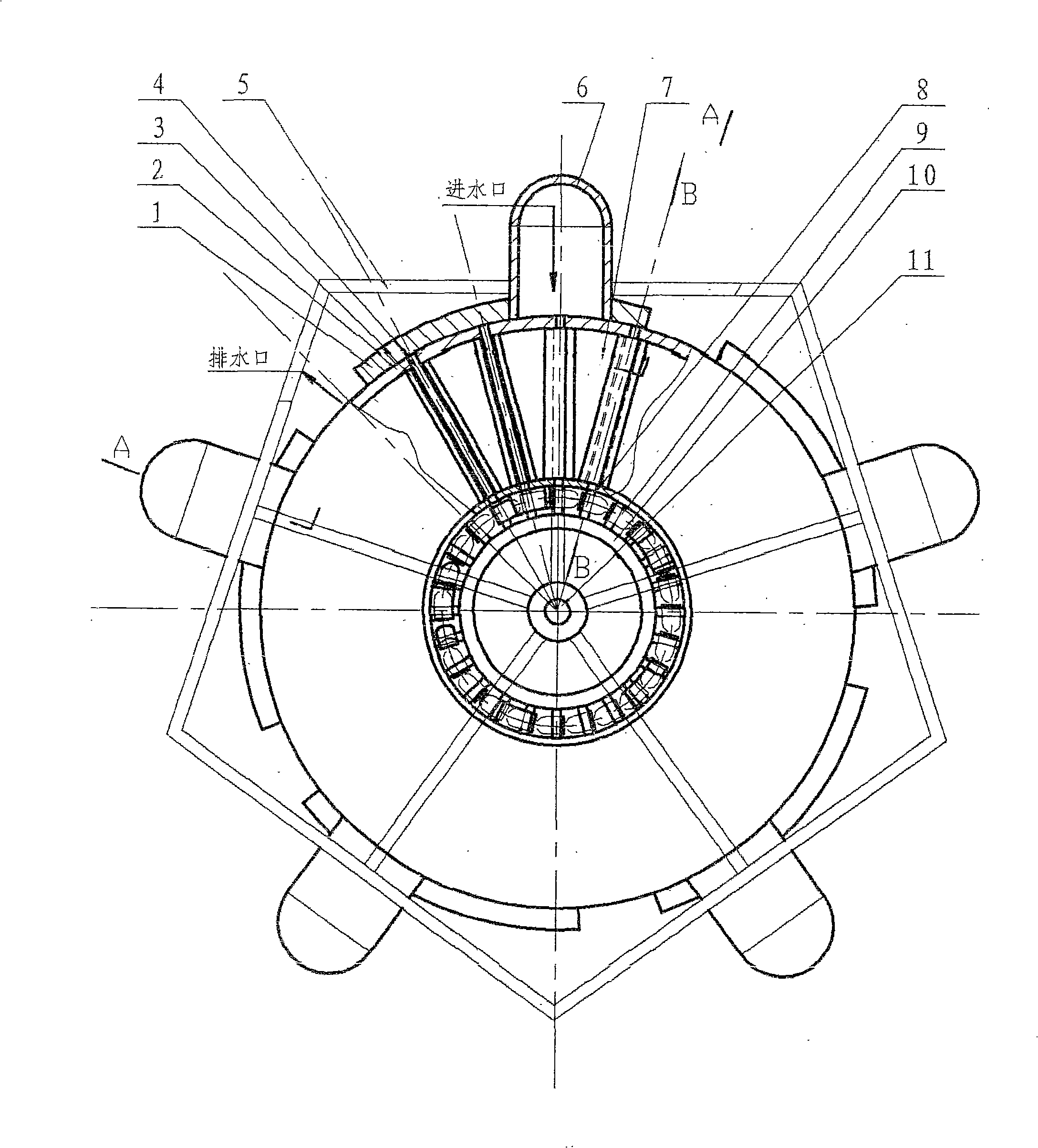
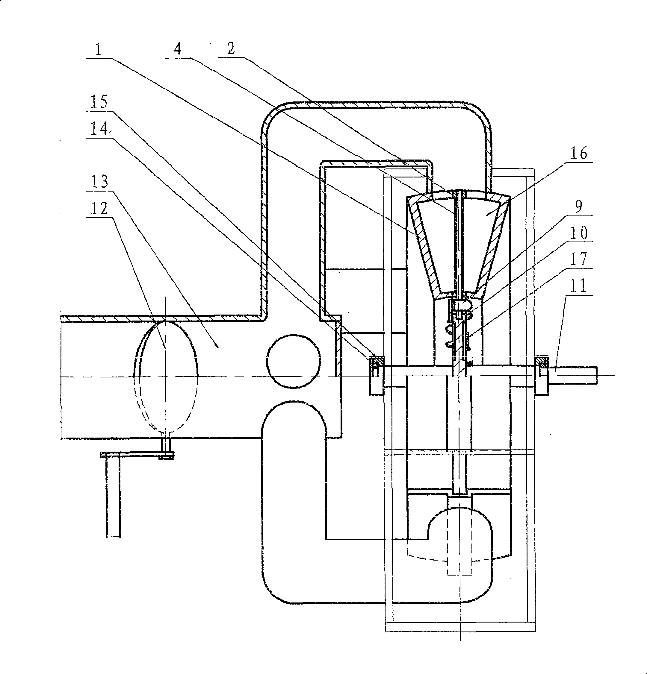
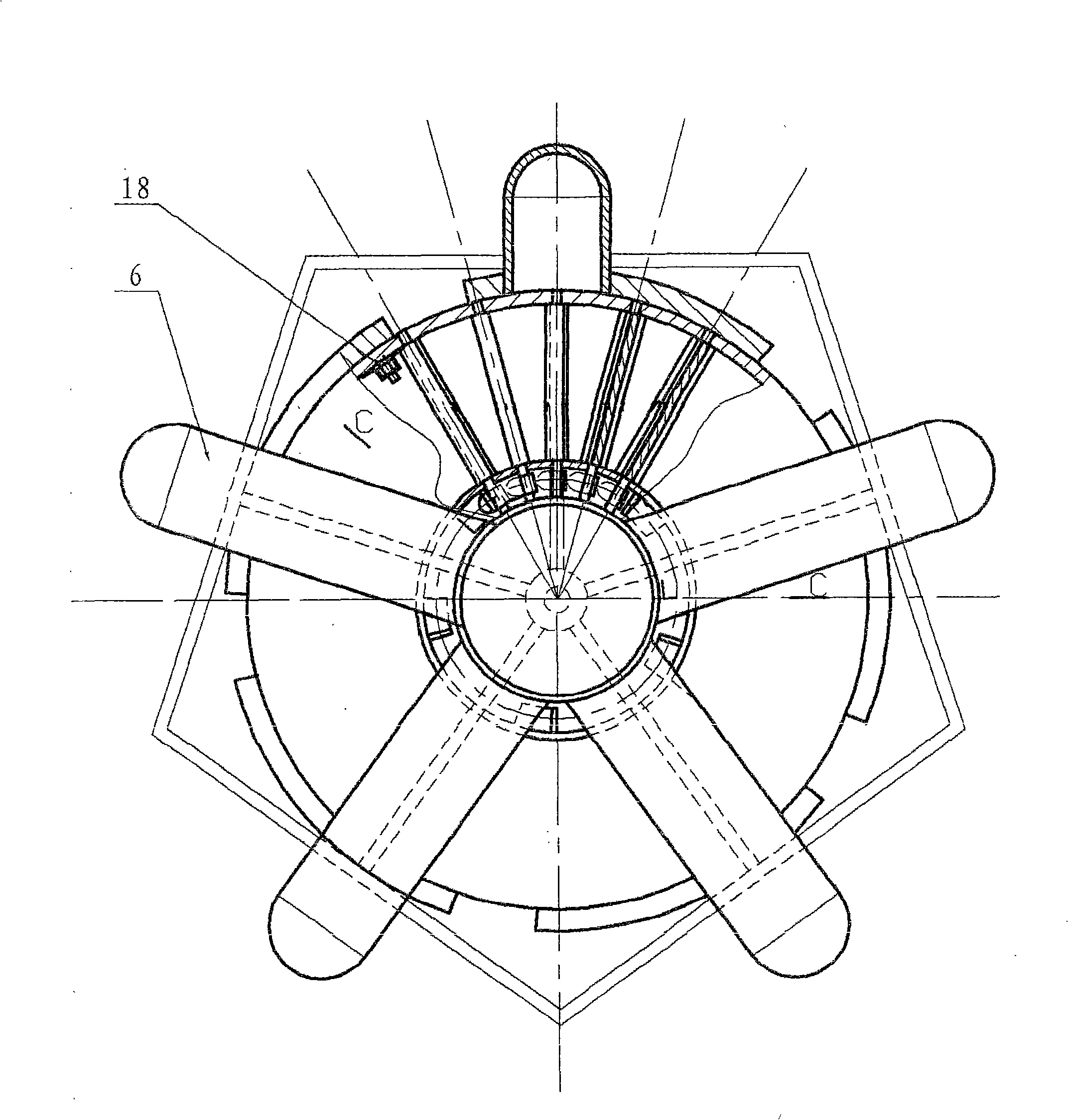
[0021] When the pressurized water passes through the control valve 12, the water divider 13 and the water inlet pipe 6 and enters the various chambers in the hydraulic casing 1, the pressurized water pushes the rotatable blade 3 that has been deployed in the chamber in the working state, and the rotatable blade 3 drives the blade wheel. And the output shaft 11 output torsion, and at the same time, due to the rotation of the blade wheel, the next rotatable blade 3 enters the chamber, the rotation key 9 of the rotatable blade 3 and the fixed key 17 are displaced, and the rotatable blade 3 is passively moved. Enter the working state at 90°; continue to push the blade wheel to rotate, the action of the rotation key 9 of the previous rotatable blade 3 and the fixed key 17 on the other side are reversed by 90° and return to the non-working state, acting on the rotation of the...


PUM


Abstract

The invention discloses a hydraulic pressure type hydraulic press which has a relatively closed shell structure, the interior of the shell of the hydraulic pressure is divided into a plurality of chambers by a plurality of watertight shutters, and a plurality of rotatable blades work simultaneously by a plurality of inlet pipes. The rotatable blades controlled by a solid key and a turning key rotate for 90 degrees after passing through the watertight shutters, so as to ensure that the press water is exerted on the surfaces of the rotatable blades; the previous rotatable blade which works reversely rotates for 90 degrees under the function of the solid key at the other side, so as to discharge the press water from an outlet, the press water enters the next chamber, the circulation is carried out repeatedly. In the hydraulic pressure type hydraulic press, the press water is exerted on a plurality of rotatable blades by a plurality of inlet pipes, a vaned wheel is driven by the hydraulic pressure to rotate so as to drive an output shaft to generate torsion, each chamber in the shell maintains at least one rotatable blade to be in operating state. When the water flows into the chamber, no splashing phenomenon occurs, which improves the water power utilization rate; the hydraulic press can generate bigger torsion without much water volume so long as the fall is big.

Description

Technical field [0001] The invention relates to a hydraulic hydraulic press. Background technique [0002] At present, the widely used hydraulic turbines all use fixed blade turbines, which use the impact generated by the water drop to drive the turbine to output torque. Since the turbine is open, splashing will occur after the water falls on it. The turbine blades are designed with an angle. When the water acts on the blades, in addition to a horizontal component that pushes the turbine to rotate, there is also a vertical component that cannot do work. Therefore, the water energy loss efficiency is large, so the water source of such a water turbine must have a large amount of water and a large drop in order to meet the requirements of the water turbine. The utilization rate of water resources is low. Summary of the invention [0003] The purpose of the present invention is to provide a hydraulic hydraulic press. Compared with the existing hydraulic turbine, it adopts a closed s...

Claims


Application Information

Patent Timeline
IPC IPC(8): F03B3/00F03B3/18F03B3/14
CPCY02E10/20
Inventor 石殿来
Owner 石殿来
Learn More