Double pole plate for fluid flow battery

A liquid flow battery and bipolar plate technology, applied in battery electrodes, fuel cell parts, hybrid batteries, etc., can solve the problems of brittle and brittle dense graphite plates, difficult battery installation process, etc., to promote electrochemical oxidation Reduction reaction, uniform distribution, effect of increasing current density

Inactive Publication Date: 2008-12-17
TSINGHUA UNIV
View PDF2 Cites 24 Cited by
  • Summary
  • Abstract
  • Description
  • Claims
  • Application Information

AI Technical Summary

Problems solved by technology

Due to the brittleness of the dense graphite plate, it is very difficult to process and prepar

Method used


Image

  • Double pole plate for fluid flow battery
  • Double pole plate for fluid flow battery
  • Double pole plate for fluid flow battery

Examples


Embodiment 1

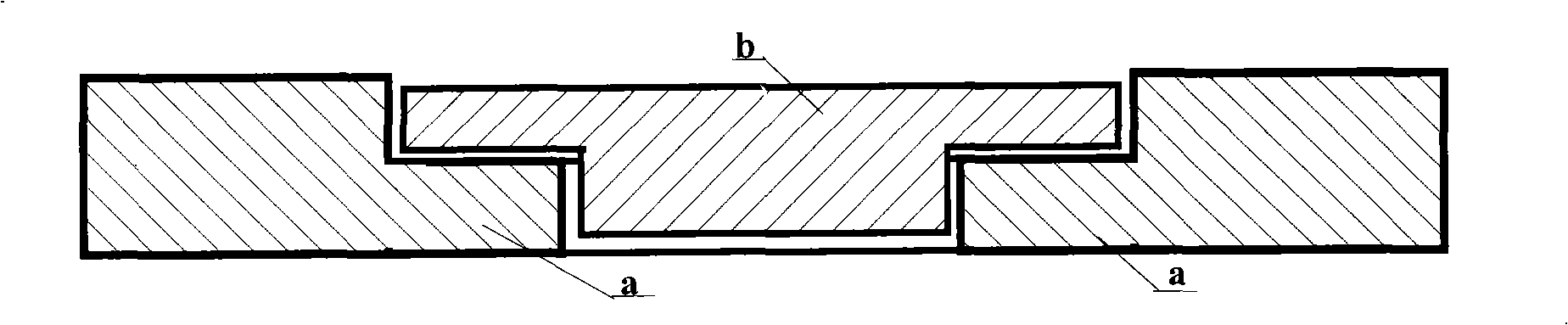
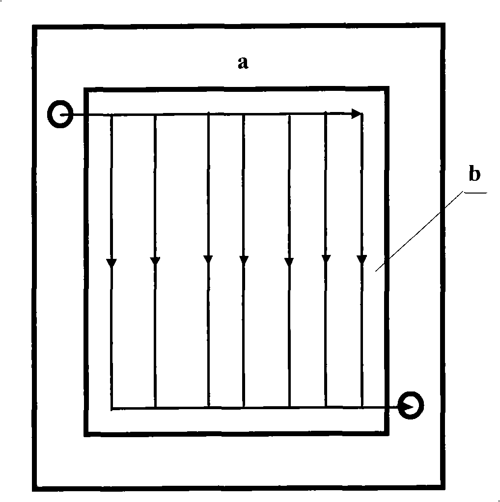
[0023] Embodiment 1: use a polyvinyl chloride engineering plastic plate with a thickness of 10mm, and a dense graphite plate with a thickness of 8mm is embedded in the middle part, and grooves with a depth of 3mm and a width of 3mm can be formed on both sides of the dense graphite plate; polyvinyl chloride engineering The plastic plate and the dense graphite plate are connected in a step-like manner, and the width of the contact surface is 10mm. The diversion grooves with the same shape on the front and rear sides of the dense graphite plate are composed of a main flow channel and parallel parallel branch flow channels connected to each other, and finally they are classified into the same main flow channel to allow the electrolyte to flow out ( figure 2 shown). Use polyvinyl chloride board bonding glue to bond the two.

Embodiment 2

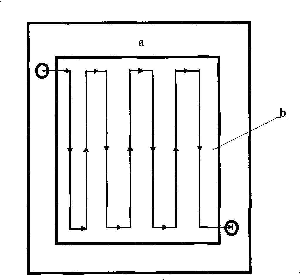
[0024] Embodiment 2: Use a polyvinyl chloride engineering plastic plate with a thickness of 10mm, and a dense graphite plate with a thickness of 8mm is embedded in the middle part, and electrolyte diversion grooves are engraved on both sides of the dense graphite plate; polyvinyl chloride engineering plastic The plate and the dense graphite plate are lapped, and the width of the contact surface is 12mm. The diversion grooves with the same shape on both sides of the dense graphite plate are composed of a meandering flow channel, the depth of the flow channel is 3 mm, and the width is 5 mm ( image 3 shown). Use polyvinyl chloride board bonding glue and epoxy resin adhesive to bond the two.

Embodiment 3

[0025] Embodiment three: use a polyvinyl chloride engineering plastic plate with a thickness of 10 mm, and insert a dense graphite plate with a thickness of 8 mm in the middle part, and electrolyte diversion grooves are engraved on both sides of the dense graphite plate; polyvinyl chloride engineering plastic The plate and the dense graphite plate are lapped, and the width of the contact surface is 12mm. The diversion grooves with the same shape on the front and rear sides of the dense graphite plate are composed of a combination of series connection and parallel connection. The depth of the flow channel is 3mm, and the width is 3mm ( Figure 4 shown). Use PVC board bonding glue and epoxy adhesive to bond the two.


PUM

PropertyMeasurementUnit
Thicknessaaaaaaaaaa
Thicknessaaaaaaaaaa

Abstract

The invention provides a bipolar plate for flow batteries, which belongs to the flow battery field. The bipolar plate for the flow batteries is characterized in that the bipolar plate comprises an engineering plastic plate and dense graphite plates embedded in the center of the engineering plastic plate in a penetrating manner. Guide grooves for anolyte and catholyte to flow through are respectively formed on the front and the rear lateral surfaces of each dense graphite plate; and two ends of each guide groove are respectively connected with through-holes on the edges of the front and the rear lateral surfaces of the engineering plastic plate, so as to allow the electrolytes to flow through. The guide grooves are connected in series or in parallel or in a mixed connection of parallel and series. The ratio of the ridge width to the groove width of the guide groove ranges from 1:0.5 to 1:6. The engineering plastic plate and the dense graphite plate are matched in a step-shaped manner therebetween, connected in a cohesion manner and sealed. The number of the dense graphite plates is more than one. The bipolar plate makes full use of the pressure resistance of the engineering plastic plate and the electric conduction property of the dense graphite plates, overcomes the disadvantage that the graphite is fragile and crisp, avoids the internal and external leakage of electrolytes and realizes the engineering enlargement of the bipolar plates for the flow batteries.

Description

technical field [0001] The invention relates to the technical field of electric energy conversion and storage, in particular to a method for manufacturing a bipolar plate of a liquid flow battery. Background technique [0002] Using renewable energy such as wind energy and solar energy to generate electricity is one of the important ways for human beings to obtain energy from nature in the future. Since the power generation of wind energy and solar energy varies significantly with day and night, it is difficult to maintain a stable power output. It needs to cooperate with a certain scale of power storage devices to form a complete power supply system to ensure continuous and stable power supply. Therefore, the development of energy storage systems with high power conversion efficiency, large storage capacity, and good economic performance has become the key to the development of renewable and clean energy. Among various forms of energy storage devices, such as water storage...

Claims


Application Information

Patent Timeline
IPC IPC(8): H01M4/00H01M4/86H01M8/02H01M12/00H01M8/0258
CPCY02E60/50
Inventor 王保国汪钱朱顺泉陈金庆龙飞
Owner TSINGHUA UNIV
Why Eureka
Try Eureka