Free ring contact type gapless sealing technology

A technology of contact sealing and sealing structure, which is applied in the directions of preventing leakage, reducing greenhouse gas, and hydroelectric power generation. It can solve the problems of reducing turbine efficiency, steam or gas leakage, etc., and achieves the effect of easy processing and lower processing accuracy requirements.

Active Publication Date: 2011-09-21
齐传正
View PDF0 Cites 0 Cited by
  • Summary
  • Abstract
  • Description
  • Claims
  • Application Information

AI Technical Summary

Problems solved by technology

[0004] For turbines, the efficiency of the turbine depends at least in part on the radial clearance between the tips of the rotating blades and the surrounding casing, on maintaining a clearance between the rotor and the diaphragm seal. If either clearance is too large, steam or gas The flow may leak through the gap, reducing the efficiency of the turbine
Additionally, if either clearance is too small, the rotor blade tips may undesirably contact the surrounding casing under certain turbine operating conditions

Method used


Image

  • Free ring contact type gapless sealing technology
  • Free ring contact type gapless sealing technology
  • Free ring contact type gapless sealing technology

Examples


Embodiment 1

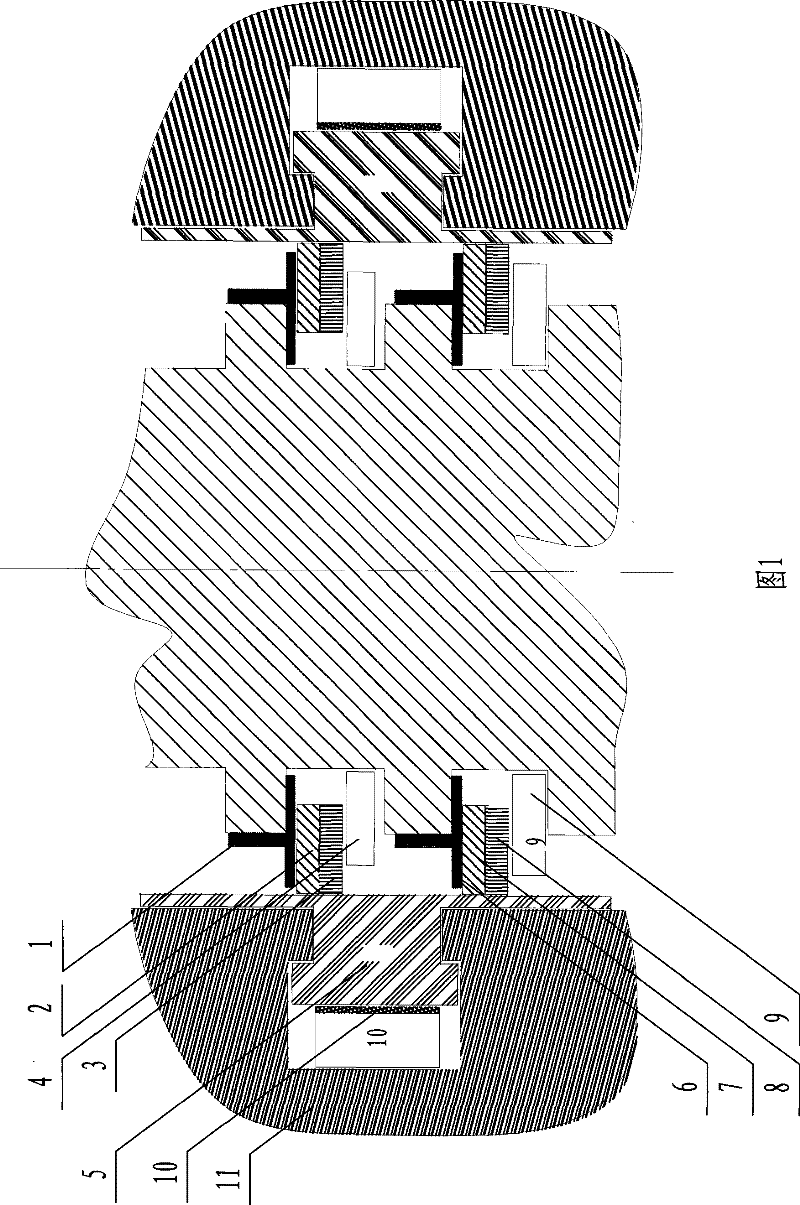
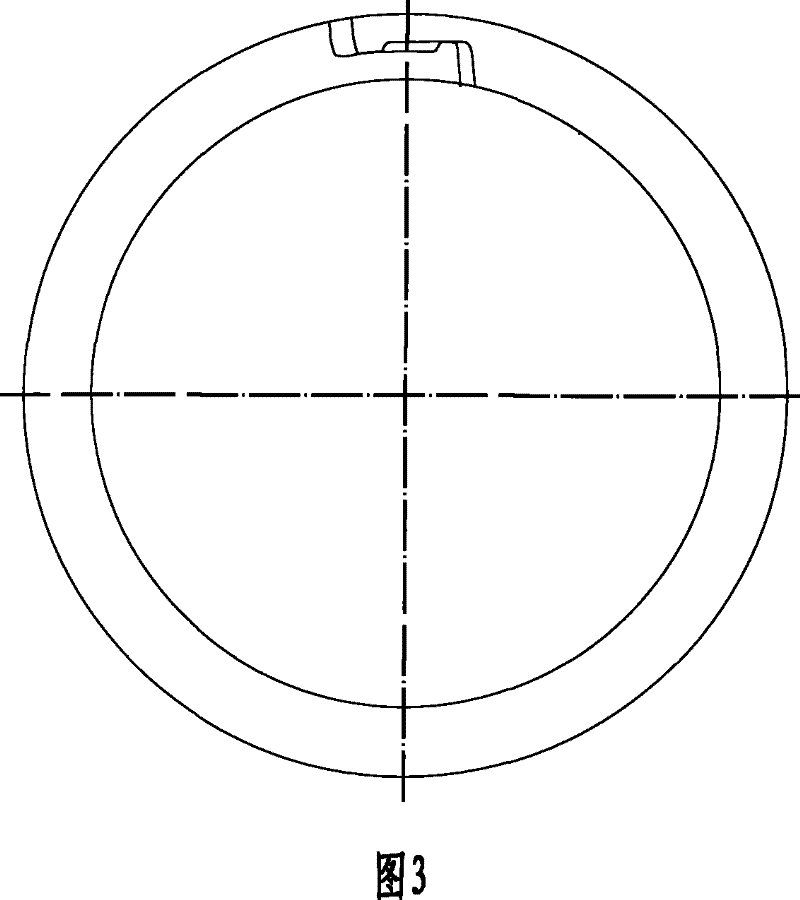
[0034] as attached figure 1 , 2 As shown, a free ring contact sealing structure of the present invention includes a seal 5 and a leaf spring 10 fixed on the turbine cylinder block or partition 11, the axial section of the seal 5 is I-shaped, and the outer surface of the seal 5 Plate springs 10 are additionally installed, and are embedded together in the T-shaped grooves of the turbine cylinder block or partition plate 11. Two groups of wear-resistant seals 1 and 6 are fixed on the rotor, and the outer surfaces of wear-resistant seals 1 and 6 are fixed. There is a gap between the circular surface and the inner circular surface of the sealing member 5 to prevent wear caused by the radial vibration of the rotor. The rotor is also provided with sealing rings that are in contact with the wear-resistant sealing bodies 1, 6 and the sealing member 5 respectively. There is also a thin steel plate spring piece 4 between the seal ring at the grinding seal body 1 and the wear-resistant s...

Embodiment 2

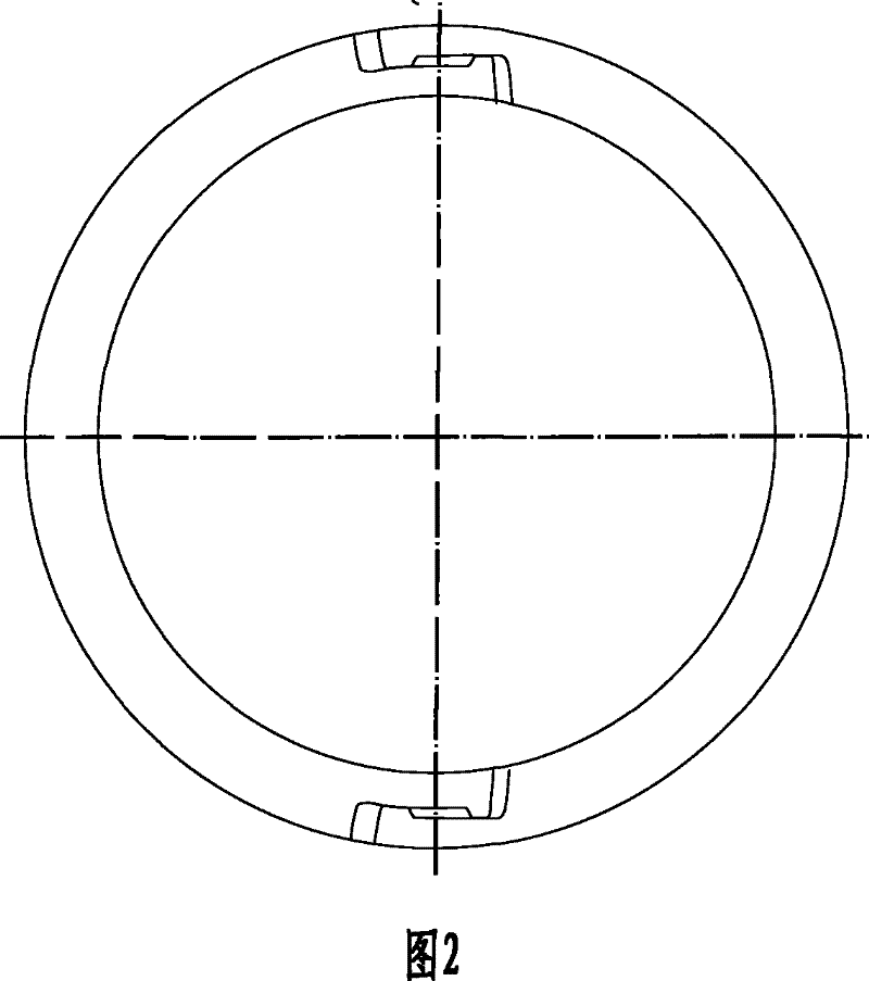
[0037] as attached figure 1 , 3 As shown, a free-ring contact sealing structure of the present invention includes a seal 5 and a leaf spring 10 in a split structure fixed on the turbine cylinder block or a partition 11, and the axial section of the seal 5 is I-shaped. A plate spring 10 is installed on its outer surface, and they are embedded together in the T-shaped groove that has been opened in the turbine cylinder block or partition plate 11. Two groups of wear-resistant sealing bodies 1, 6 are fixed on the rotor, and the wear-resistant sealing body There is a gap between the outer circular surfaces of 1 and 6 and the inner circular surface of seal 5 to prevent wear caused by the radial vibration of the rotor. A thin steel spring sheet 4 is also arranged between the sealing ring near the wear-resistant sealing body 1 and the wear-resistant sealing body 6, and a thin steel spring sheet 9 is arranged on the side of the sealing ring near the wear-resistant sealing body 6, Th...


PUM


Abstract

The invention provides a contact-type seamless sealing structure of a free ring, belonging to the steam turbine steam seal technical field. The structure comprises a sealing member and a board spring fixed on the turbine cylinder or on a clapboard, wherein, the axial cross section of the sealing member is I-shaped, a board spring is arranged on the outside circular surface, and the sealing member and the board springs are embedded in the T-slots of the turbine cylinder or the clapboard; at least one set of wear-resistant seals are fixed on the rotor, wherein, a space is arranged between the outside circular surface of the wear-resistant seals and the inside circular surfaces of the seals; a gasket ring contacting the wear-resistant seals and the seals are arranged on the rotor, wherein, the other free plane of the gasket ring contacts a thin sheet leaf spring arranged on the rotor. The gasket ring comprises at least two seal rings which are capable of moving freely in both the radial and the axial directions. The seamless sealing structure of the invention achieves the purposes of both sealing and free movement, ensures that the rotating shaft causes no damage to the seals no matter in radial vibration or axial float, thus achieving long lasting and durable sealing and long-term guaranteeing of the sealing quality. The invention is applicable to the sealing of the parts between loose axles and static cylinder sleeves of steam turbines, hydraulic turbines and turbines.

Description

(1) Technical field [0001] The invention relates to a steam seal improvement technology of a steam turbine, a water turbine or a turbine, in particular to a shaft seal, a diaphragm seal, a shroud seal and a water turbine for the high, medium and low pressure cylinders of a steam turbine, a turbine or a turbo compressor The free ring contact type gapless sealing structure is suitable for all water seals. (2) Background technology [0002] It is known that the high-temperature and high-pressure gas used to do work inside the steam turbine is sealed by the seal ring. In this seal method, there is a gap of 0.3mm to 1.0mm between the seal ring and the rotating shaft, so the sealing effect Poor, directly affect the working efficiency of the steam turbine. In addition, the rotor, steam seal, and cylinder of the steam turbine must be processed with high precision because they are sealed, and the installation precision is high. [0003] For water turbines, the size of the gap betwe...

Claims


Application Information

Patent Timeline
Patent Type & Authority Patents(China)
IPC IPC(8): F01D11/12F03B11/00
CPCY02E10/226Y02E10/20
Inventor 齐传正
Owner 齐传正
Why Eureka
Try Eureka