Construction method for paving road slot minitype communication pipe by urban area road

A construction method and road technology, applied in the direction of optical fiber/cable installation, etc., can solve the problems of insufficient detection capability of micro-control pipe jacking equipment, reduced advantages of network expansion, and danger of micro-control pipe jacking operations, etc., to achieve easy repair and construction risk The effect of small size and flexible construction

Active Publication Date: 2008-12-24
HANDAN BRANCH OF CHINA MOBILE GRP HEBEI COMPANYLIMITED +1
View PDF0 Cites 4 Cited by
  • Summary
  • Abstract
  • Description
  • Claims
  • Application Information

AI Technical Summary

Problems solved by technology

Although this construction method has the advantages of short construction time and flexibility, because the road trench laying method is one-time, compared with the gradual installation of air-blown micro-cables, the advantages for future network expansion are significantly reduced, and when a fault occurs, the optical cable not easy to replace
[0004] The existing micro-control pipe jacking method for the laying of road trench optical cables is limited due to the influence of complex underground pipelines during construction in urban areas, and the detection capability of micro-control pipe jacking equipment is insufficient. Make the micro-control pipe jacking operation very dangerous

Method used


Image

  • Construction method for paving road slot minitype communication pipe by urban area road
  • Construction method for paving road slot minitype communication pipe by urban area road
  • Construction method for paving road slot minitype communication pipe by urban area road

Examples


Embodiment Construction

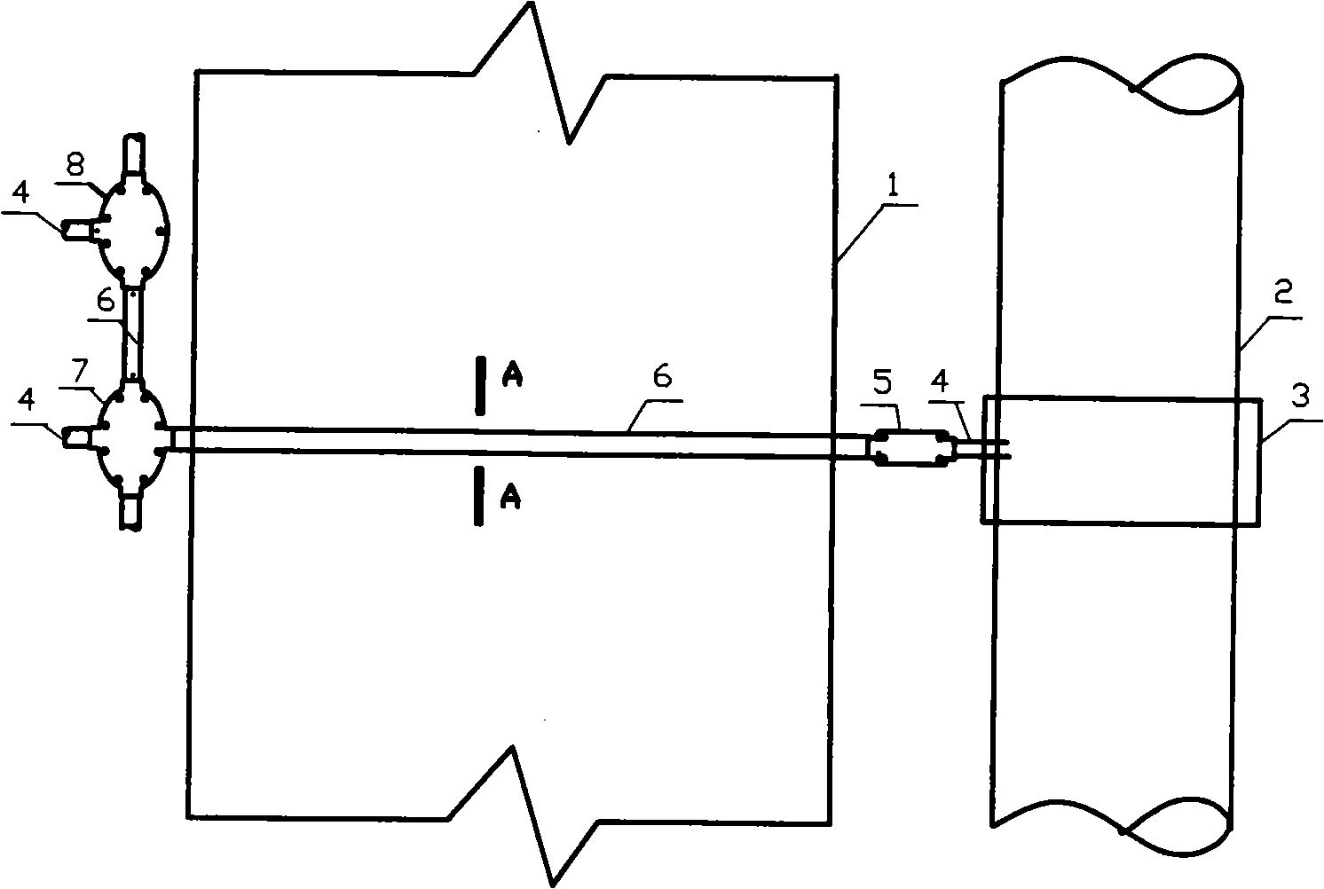
[0027] The present invention proposes the construction method of laying the micro-communication pipeline of the road groove by using urban roads, and its construction schematic diagram is as follows figure 1 shown, including the following steps:

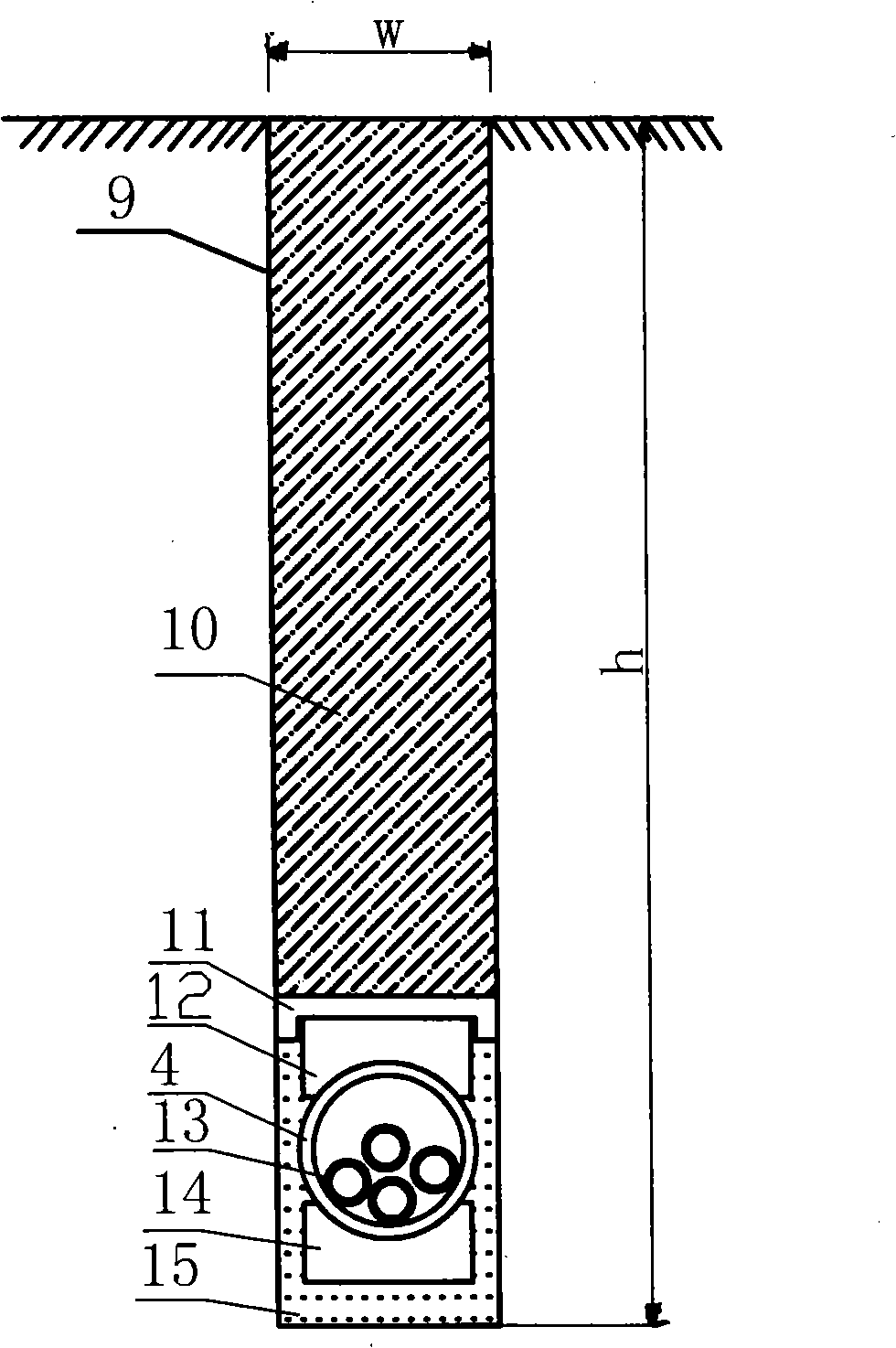
[0028] (1) According to the set plan or design route, draw a groove line on the road 1, cut the road surface along the drawn groove line, dig out the groove 9, and make the bottom of the groove smooth;

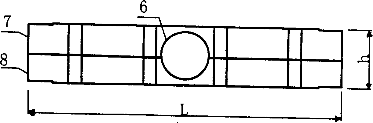
[0029] (2) Embed a four-way micropipe branching box 7 or a three-way micropipe branching box 8 at one end of the groove 9, and embed a micropipe joint box 5 near the manhole 3 or the transfer box at the other end of the groove;

[0030] (3) spread fine sand 15 at the bottom of described groove 9, as figure 2 As shown, the thickness is 5 to 15 mm, and the pipe support 14 is laid flat on the fine sand, and the optical cable sub-tube 4 is placed on the pipe support 14 in the groove 9, and the two ends of the micro-cable sub-tube 4 are...


PUM


Abstract

The invention relates to a construction method for paving a road trough micro-communication pipeline by utilizing a city road, belonging to the optical fiber cable transmission technology field. A trough line is firstly drawn according to a set planning or a designed router, a road surface is cut along the drawn trough line, and a trough is dug out; a four-way or three-way micro-pipe is embedded at one end of the trough, and a micro-pipe joint box is embedded at the other end of the trough which is close to a manhole or a connection box; a pipe bracket is paved at the bottom part of the trough, a micro-cable sub-pipe is distributed on the pipe bracket, the both ends of the micro-cable sub-pipe are extended into the micro-pipe joint box and a micro-pipe branch box; an upper pipe cover is arranged above the sub-pipe, a cover board is finally covered on the pipe cover; and a super early strength repairing agent is poured into the trough. The construction method has the advantages that: the application range is wide, the construction method can be accessed to the tail end of a metropoliatan area network for communicating the prior communication pipeline and a small-diameter rain (polluted) water pipeline, thereby building the supplement for a micro-pipeline system. The advantage of the network capacity expansion is obvious, when in fault of the optical fiber cable, the rush repair is easy, and the recovery of the communication is fast. The construction is flexible and not limited by an underground pipe network, and the construction risk is very small.

Description

technical field [0001] The invention relates to a construction method for laying road groove micro-communication pipes by utilizing urban roads, and belongs to the technical field of optical cable transmission. Background technique [0002] In the construction of traditional optical cable transmission network, firstly, the roads or sidewalks in urban areas are broken and trenched, and the communication pipelines are pre-buried underground, and then ordinary optical cables are laid in the pipelines by manual traction. [0003] Existing road groove optical cable construction method is to open a narrow slit on the urban road surface, and bury an optical cable in the slit. Although this construction method has the advantages of short construction time and flexibility, because the road trench laying method is one-time, compared with the gradual installation of air-blown micro-cables, the advantages for future network expansion are significantly reduced, and when a fault occurs, t...

Claims


Application Information

Patent Timeline
Patent Type & Authority Applications(China)
IPC IPC(8): G02B6/50G02B6/46
Inventor 李强王胜明王军于涛马国博白俊峰姜长青董宝义
Owner HANDAN BRANCH OF CHINA MOBILE GRP HEBEI COMPANYLIMITED
Why Eureka
Try Eureka