Fingerprint identification method combining point with line
A technology of fingerprint identification and dot-line, which is applied in the field of biometrics, can solve the problems of large influence of false feature points, poor anti-noise ability, and easy to cause misjudgment, etc., to reduce the influence of false feature points, strong anti-noise ability, The effect of improving reliability
- Summary
- Abstract
- Description
- Claims
- Application Information
AI Technical Summary
Problems solved by technology
Method used
Image
Examples
specific Embodiment approach 1
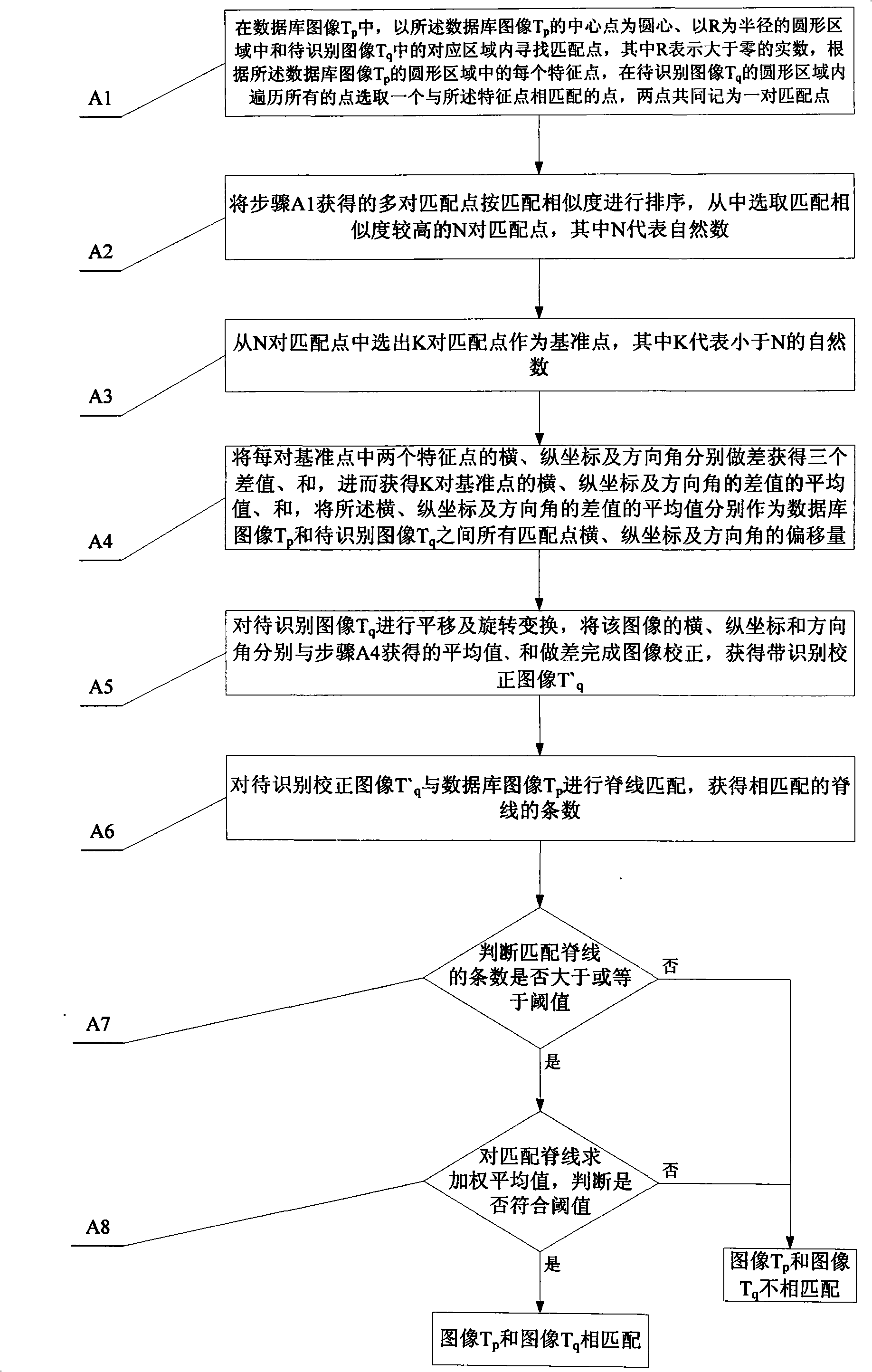
[0016] Specific implementation mode one: see figure 1 , this embodiment consists of the following steps:
[0017] Step A1, in the database image T p , taking the database image T p The center point of is the center of the circle, the circular area with R as the radius and the image to be recognized T q Look for matching points in the corresponding area in , wherein R represents a real number greater than zero, and the selection of the R value should ensure that there are three to five feature points in the circular area. According to the database image T p Each feature point in the circular area, in the image to be recognized T q Traverse all the points in the circular area to select a point that matches the feature point, and the two points are collectively recorded as a pair of matching points;
[0018] Step A2, sorting the pairs of matching points obtained in step A1 according to matching similarity, and selecting N pairs of matching points with higher matching similari...
specific Embodiment approach 2
[0025] Specific implementation mode two: this implementation mode further illustrates on the basis of specific implementation mode one that the specific method for sorting the matching points according to the matching similarity described in step A1 is:
[0026] Step B1, comparing the database image T p and the image to be recognized T q Four feature quantities of two feature points in the circular area in : feature point type, distance from feature point to center of circle, frequency at feature point and difference between feature point orientation angle and circle center orientation angle, use P={ P 1 ,P 2 ...P N}, Q={Q 1 , Q 2 ...Q N} respectively represent the database image T p and the image to be recognized T q A collection of feature points in the circular area;
[0027] Step B2, select a feature point P in the set P i , to traverse all the feature points in the set Q, for any feature point Q in the set Q j , respectively judge the feature point P i with Q ...
specific Embodiment approach 3
[0033] Specific implementation mode three: This implementation mode further illustrates on the basis of specific implementation mode one that the specific method of sorting the feature points described in step A2 according to similarity is:
[0034] Step C1, calculate each pair of matching points P i and Q j The frequency difference Δf, the feature point P i and Q j The distance difference to their respective centers (d i -d j ) and the feature point P i and Q j The difference of the direction angle of (θ i -θ p )-(θ j -θ q );
[0035] Step C2, find the largest frequency difference max|Δf| and the largest distance difference max|d among N pairs of matching points i -d j The difference between | and the maximum direction angle max|(θ i -θ p )-(θ j -θ q )|;
[0036] Step C3, according to the parameters obtained in step C2 by the formula |Δf / maxΔf|+|(d i -d j ) / max(d i -d j )|+|[(θ i -θ p )-(θ j -θ q )] / max[(θ i -θ p )-(θ j -θ q )]|Obtain the similari...
PUM
 Abstract
Description
Claims
Application Information
 - R&D
- Intellectual Property
- Life Sciences
- Materials
- Tech Scout
- Unparalleled Data Quality
- Higher Quality Content
- 60% Fewer Hallucinations
Browse by: Latest US Patents, China's latest patents, Technical Efficacy Thesaurus, Application Domain, Technology Topic, Popular Technical Reports.
© 2025 PatSnap. All rights reserved.Legal|Privacy policy|Modern Slavery Act Transparency Statement|Sitemap|About US| Contact US: help@patsnap.com

