Welding torch and end piece and also contact tube for a welding torch

A technology of tail end piece and conductive tube, applied in the field of welding torch, can solve the problems such as can not be compensated, reduce the service life of the conductive tube, and the welding wire wears a lot, etc. Effect

Active Publication Date: 2008-12-24
FRONIUS INTERNATIONAL GMBH
View PDF3 Cites 5 Cited by
  • Summary
  • Abstract
  • Description
  • Claims
  • Application Information

AI Technical Summary

Problems solved by technology

[0007] U.S. Patent 6495798B1 also discloses a transition element for a device that guides welding wire to a conductive tube, where the wear of the welding wire is high, so that the conductive tube must be replaced frequently
[0008] Finally, WO 2003 / 039800 A1 discloses a conductive tube with holes for guiding the welding wire, which also does not take measures to prevent "narrowing" due to abrasion of the welding wire
[0009] Here, it is disadvantageous that the transition element is firmly connected to the conductive tube, so that, for example, increased bending leads to more wear, since the bending can only be straightened, not compensated
Abrasive deposits in the conductive tube lead to narrowing and thus significantly reduce the service life of the conductive tube
Also, on the downside, the transition element is made of a non-conductive material that cannot form a secondary contact with the wire
Therefore, there is an increased risk of the wire getting "stuck" in the conductive tube

Method used


Image

  • Welding torch and end piece and also contact tube for a welding torch
  • Welding torch and end piece and also contact tube for a welding torch
  • Welding torch and end piece and also contact tube for a welding torch

Examples


Embodiment Construction

[0049] First of all, it is pointed out that the same reference numerals refer to the same components in the exemplary embodiments.

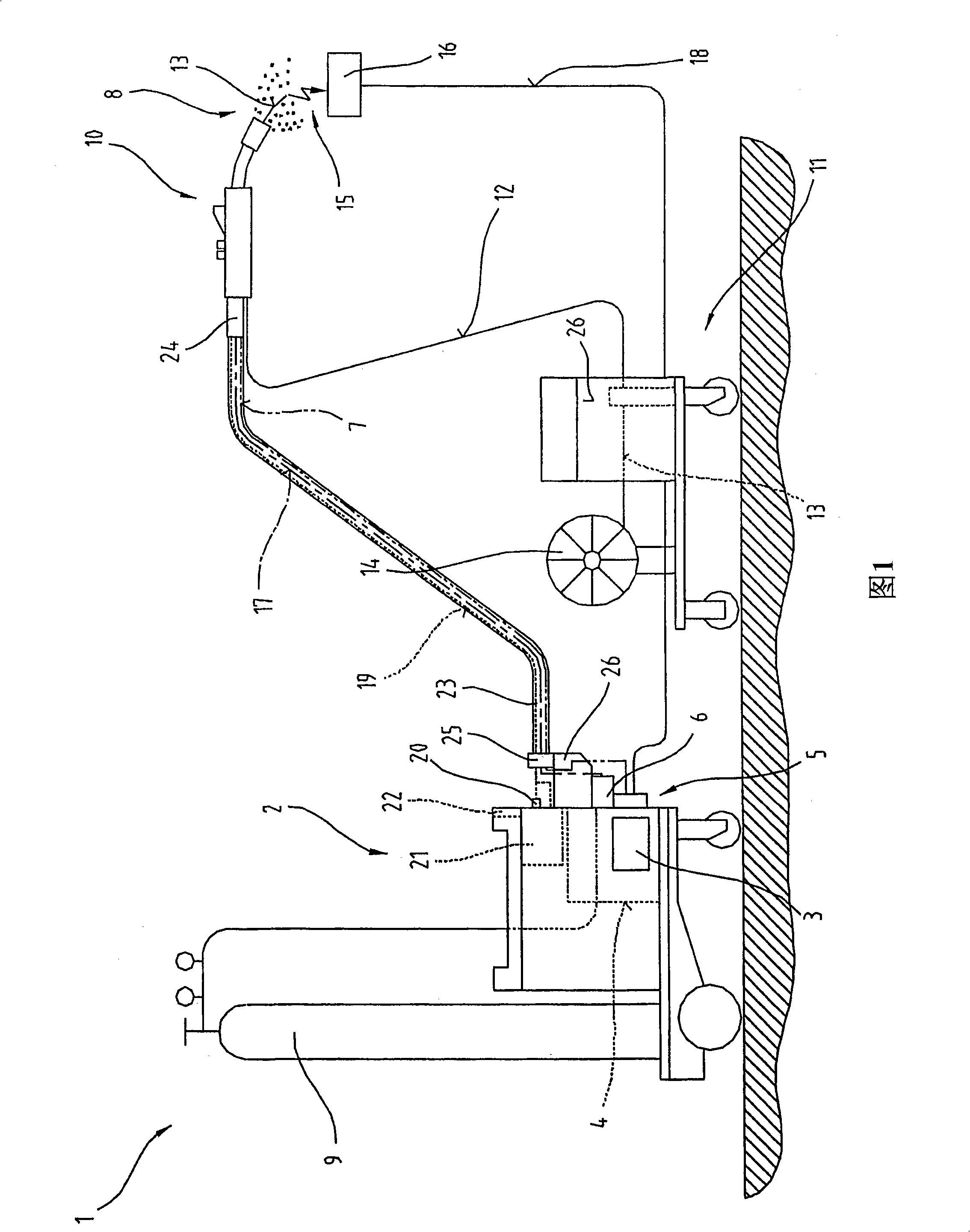
[0050]Figure 1 shows a welding device 1 or welding equipment for various welding processes or methods, such as MIG / MAG welding, or WIG / TIG welding, or arc welding methods, twin wire / front and rear wire welding method, plasma welding or brazing, etc.

[0051] The welding device 1 includes a power source 2 including a power element 3 , a control device 4 and a switching member 5 associated with the power element 3 and the control device 4 . The switching element 5 and the control device 4 are connected to a control valve 6 arranged in a supply line 7 for a gas 8, in particular a shielding gas such as carbon dioxide, between the gas container 9 and the welding torch 10 or welding torch , helium, argon, etc.

[0052] In addition to this, the wire feeder 11 normally used for MIG / MAG welding can also be activated by the control device 4, and addition...


PUM


Abstract

The invention relates to a welding torch (10) having a torch body (46) in which at least one device (32) for feeding a welding wire (13) and a contact tube (30) having a bore (33) and a guide bore (34), running concentrically thereto, for guiding the welding wire (13) in the direction of a workpiece (16) are arranged, wherein the welding wire (13) can be supplied with electrical energy via the contact tube (30), wherein one end of the feed device (32) is arranged in the guide bore (34) of the contact tube (30) and is provided with an electrically conductive end piece (36) having a bore (40) for the welding wire (13). To provide such a welding torch (10) in which the durability or the service life of the wearing parts, in particular of the contact tube (30), is prolonged, provision is made for the end piece (36) of the feed device (32) to be movably arranged in the guide bore (34) of the contact tube (30).

Description

technical field [0001] The invention relates to a welding torch having a torch body provided with: at least one device for feeding welding wire; and a conducting tube having a concentric extension with the conducting tube for guiding the welding wire towards the workpiece One end of the delivery device is arranged in the guide hole of the conductive tube and is provided with a conductive end piece having a hole for passing the welding wire. [0002] The invention also relates to an end piece for a feeding device for feeding welding wire into a welding torch, the end piece being fixable to that end of the feeding device which is positioned in the guide hole of the conductive tube. [0003] The invention also relates to a conductive tube having a hole for passing the welding wire and a guide hole for receiving the conveyed welding wire and forwarding it into the aforementioned hole. Background technique [0004] Welding torches are known in which a conductive tube is firmly f...

Claims


Application Information

Patent Timeline
Patent Type & Authority Applications(China)
IPC IPC(8): B23K9/00B23K9/12B23K9/29B23K9/26
CPCB23K9/295
Inventor 约瑟夫·阿特尔斯梅尔安德烈亚斯·莱昂哈特斯贝戈约尔格·卡兹梅尔
Owner FRONIUS INTERNATIONAL GMBH
Why Eureka
Try Eureka