
Anti-sloshing device in moon pool

A moon pool and ship bow technology, which is applied in the field of anti-sloshing devices in the moon pool, can solve the problems of reduced worker safety and work efficiency, reduced speed, hull damage, etc. Effect

Active Publication Date: 2008-12-24
SAMSUNG HEAVY IND CO LTD
View PDF0 Cites 22 Cited by
  • Summary
  • Abstract
  • Description
  • Claims
  • Application Information

AI Technical Summary

Problems solved by technology

The moon pool is indispensable for the function of the drill ship, but from the viewpoint of mooring the ship, sailing stability of the ship, and sailing performance, the moon pool becomes a weak point
[0008] Specifically, in a conventional drilling ship, due to the sloshing phenomenon caused by the relative motion between the seawater in the moon pool and the seawater outside the ship, when the drilling ship travels, resistance increases, its speed decreases, and power consumption increases , increased fuel consumption and damage to the hull
[0009] Furthermore, in the case of conventional drillships, due to the movement of seawater in the moon pool, seawater may overflow onto the ship, resulting in reduced worker safety and work efficiency

Method used


Image

  • Anti-sloshing device in moon pool
  • Anti-sloshing device in moon pool
  • Anti-sloshing device in moon pool

Examples


no. 1 example

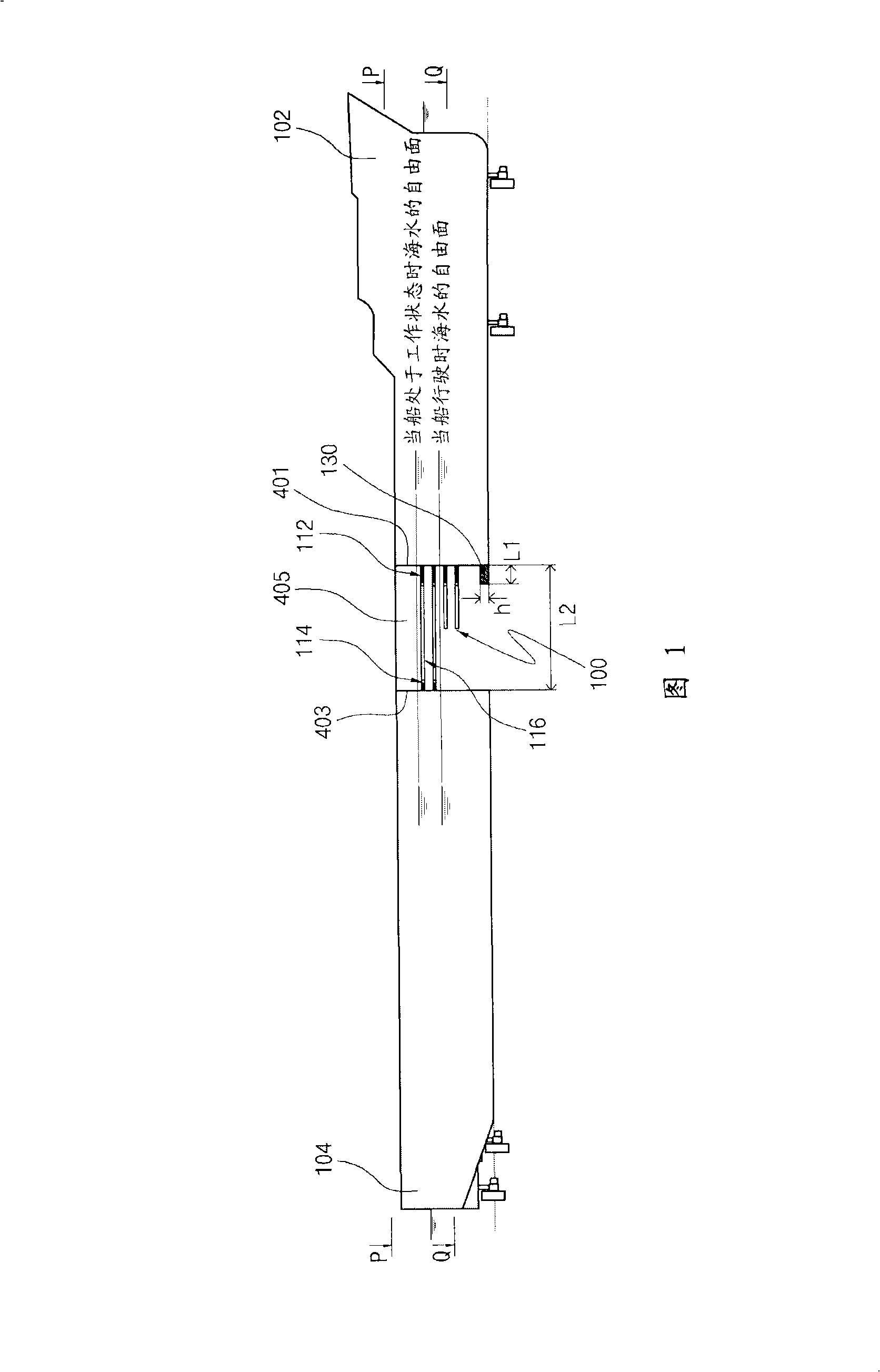
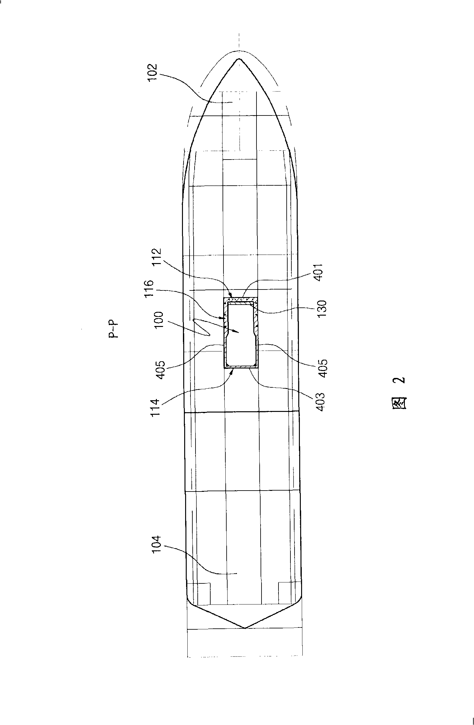
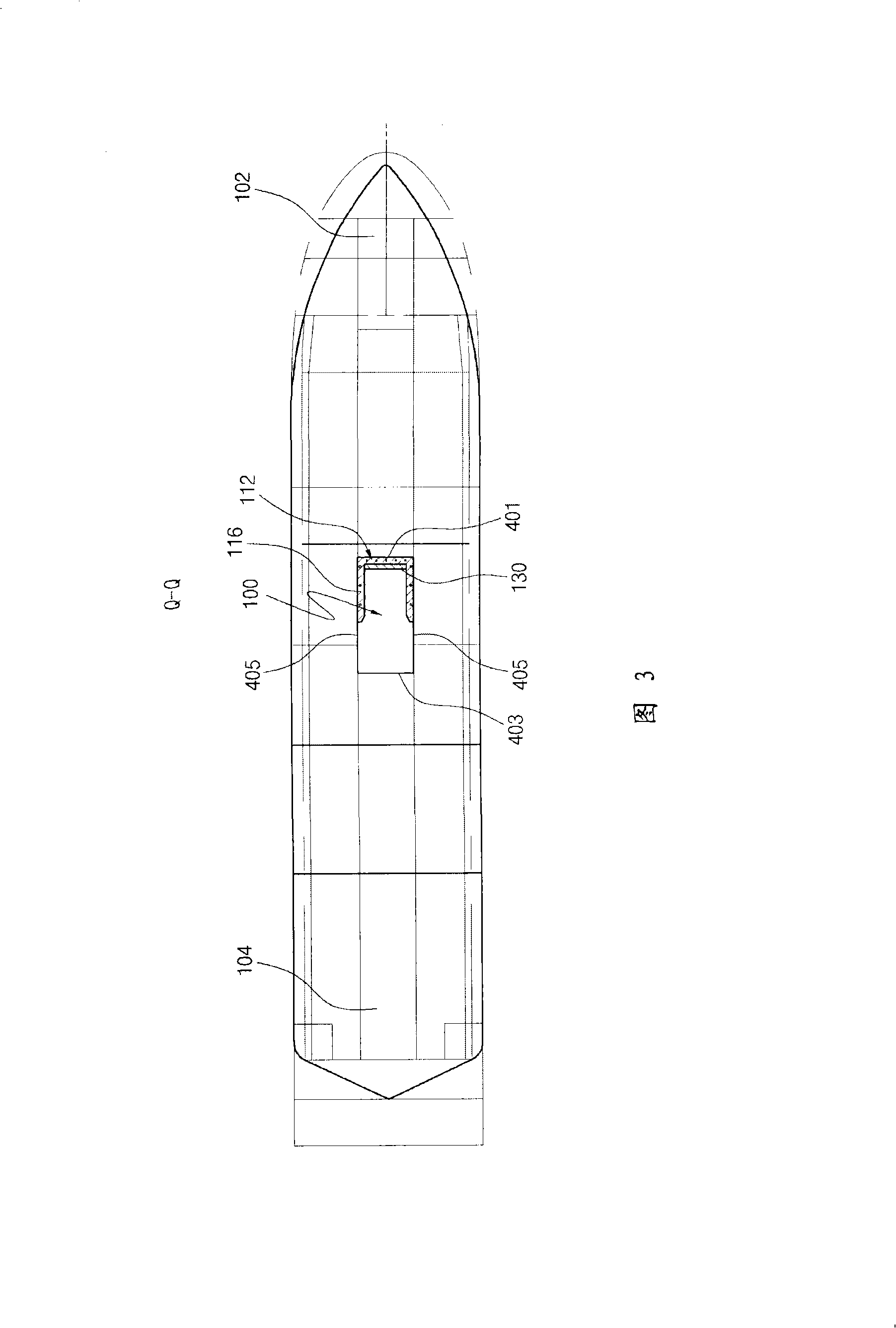
[0040] FIG. 1 is a side sectional view showing a ship having an anti-sloshing moonpool structure according to a first embodiment of the present invention. FIG. 2 is a top sectional view taken along line P-P of FIG. 1 . FIG. 3 is a top sectional view taken along line Q-Q of FIG. 1 . FIG. 4 is a perspective view showing a part of the first embodiment of FIG. 1 .

[0041] As shown in FIG. 1 , according to the position in the ship, the ship having the anti-sloshing moonpool structure according to the present invention is divided into: a bow part 102 forming the front of the ship; a stern part 104 forming the rear part of the ship; a moon pool 100 , formed between the bow portion 102 and the stern portion 104 .

[0042] The moon pool 100 is formed vertically through the ship from the top of the ship to the bottom of the ship, and the moon pool 100 is used as a passage through which drilling machinery and drilling pipes reach the seabed.

[0043] The anti-sloshing moonpool struct...

no. 2 example

[0071] The anti-sloshing moonpool structure according to the second embodiment of the present invention is configured such that the protruding length of the moonpool panels decreases from the top of the ship to the bottom of the ship so that the maximum working area expands toward the bottom of the ship. The technical spirit is the same as or similar to that of the first embodiment. Therefore, in Figure 1 to Figure 7 The same reference numerals are used throughout the different drawings to indicate the same or similar parts. Also, explanations of these components will be omitted.

[0072] Figure 5 and Image 6 As shown, several pool panels 212, 214 and 216 are vertically bonded to the bow side wall 401 and the stern side wall 403 respectively from the top of the ship to the bottom of the ship at positions spaced apart from each other at predetermined intervals along the height direction of the ship. and on the opposite side walls 405 .

[0073] refer to Image 6 , the term...


PUM


Abstract

An anti-sloshing moon pool structure is disclosed. The anti-sloshing moon pool structure of the present invention includes moon pool plates (112, 114 and 116), which are provided on a bow-side wall (401), a stern-side wall (403) and opposite sidewalls (405) of a moon pool (100), and a moon pool bottom block (130), which is provided on a bow-side lower edge (407) of the moon pool (100). The moon pool plates and the moon pool bottom block have protruding lengths within which they do not interfere with a maximum working area. Upper steps (112a, 112b, 114a, 114b, 116a, 116a-l, 116b and 116b-l) of the moon pool plates are disposed such that, when a ship is in a working position, they are lower than the free surface of the seawater, and lower steps (112c, 112d, 116c and 116d) of the moon pool plates are disposed such that, when the ship runs, they are lower than the free surface of the seawater.

Description

technical field [0001] The invention relates to a ship with an anti-sloshing moonpool structure. Background technique [0002] In accordance with rapid international industrialization and technological development, the use of earth's resources (eg, oil) is increasing. Therefore, from a global perspective, the stable production and supply of oil has become a very important matter. [0003] To this end, there has been increased focus on the development of small marginal or deepwater fields, which were once dismissed due to their low potential returns. Therefore, with the development of offshore drilling technology, drilling ships with drilling equipment suitable for developing such subsea oil fields have been proposed and developed. [0004] In the traditional oil drilling technology, a drilling ship (rig ship) or a fixed platform is mainly used, and the drilling ship or fixed platform can only be moved by a tugboat, and is moored at a certain position in the sea with a moor...

Claims


Application Information

Patent Timeline
Patent Type & Authority Applications(China)
IPC IPC(8): B63B35/44
CPCB63B35/4413B63B39/06B63B2003/147B63B1/32B63B35/44B63B43/00
Inventor 安映奎金泓秀金圣洙朴钟镇
Owner SAMSUNG HEAVY IND CO LTD
Learn More