Fastener device for connecting and detaching bore rod

A clamping device and drill pipe technology, which is applied in the direction of drill pipe, drill pipe, drilling equipment, etc., can solve the problems of reducing cost, simplifying operation, reducing drilling rig space, compact structure, and can only be used for flanged drill pipe, etc. , to achieve the effects of easy automatic operation, optimized removal of obstacles, and good mechanical effects

Inactive Publication Date: 2008-12-31
CITIC HEAVY INDUSTRIES CO LTD +1
View PDF0 Cites 7 Cited by
  • Summary
  • Abstract
  • Description
  • Claims
  • Application Information

AI Technical Summary

Problems solved by technology

With the advancement of technology and the improvement of the structure of the drilling rig, the original equipment seriously affects the improvement of the structure of the drilling rig, which restricts the reduction of the space and compact structure of the drilling rig, which in turn affects the reduction of cost and simplification of operation.
[0004] In the past, the engagement mechanism of shaft drilling rigs was mostly driven by cylinders, and the engagement mechanism and the reserved platform were in surface contact. In this way, when the engagement mechanism and the reserved platform are in surface contact, the friction force during the opening and closing process of the engagement mechanism is relatively large, and the wear is serious. , and often fail to reach the position during the closing process of the clutch mechanism, requiring manual assisted closing
Moreover, in the past, the cohesive mechanism was only designed for one type of drill pipe. For example, the flanged drill pipe can only be used for the flanged drill pipe, and the clamped drill pipe can only be used for the toothed drill pipe.

Method used


Image

  • Fastener device for connecting and detaching bore rod
  • Fastener device for connecting and detaching bore rod
  • Fastener device for connecting and detaching bore rod

Examples


Embodiment Construction

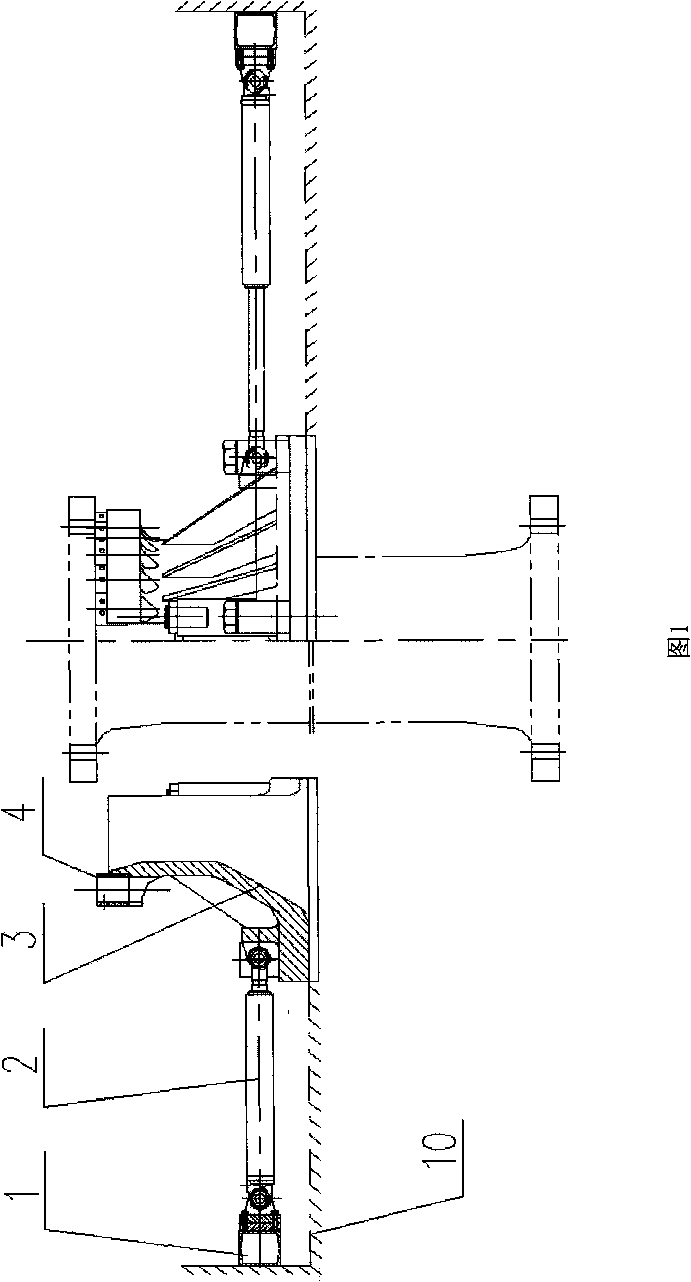
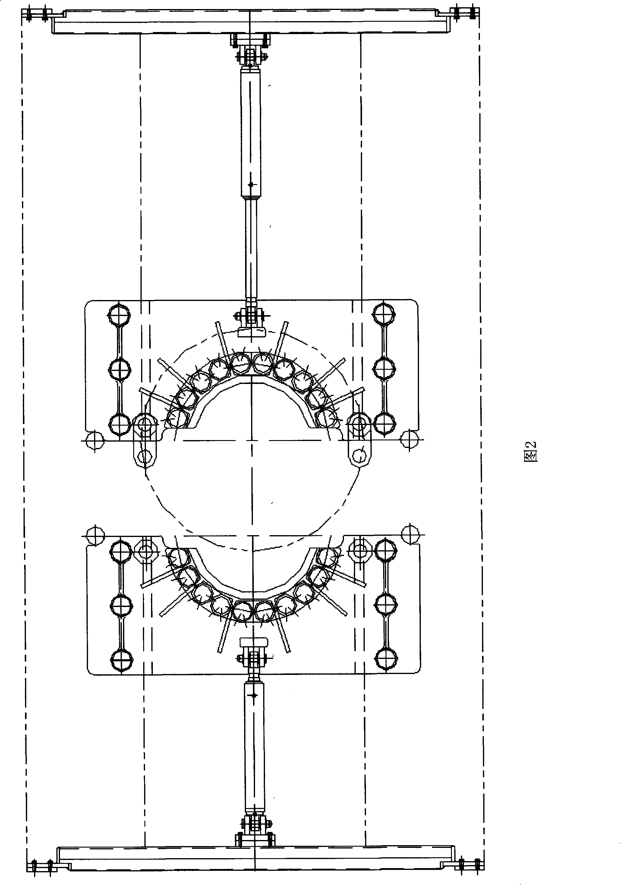
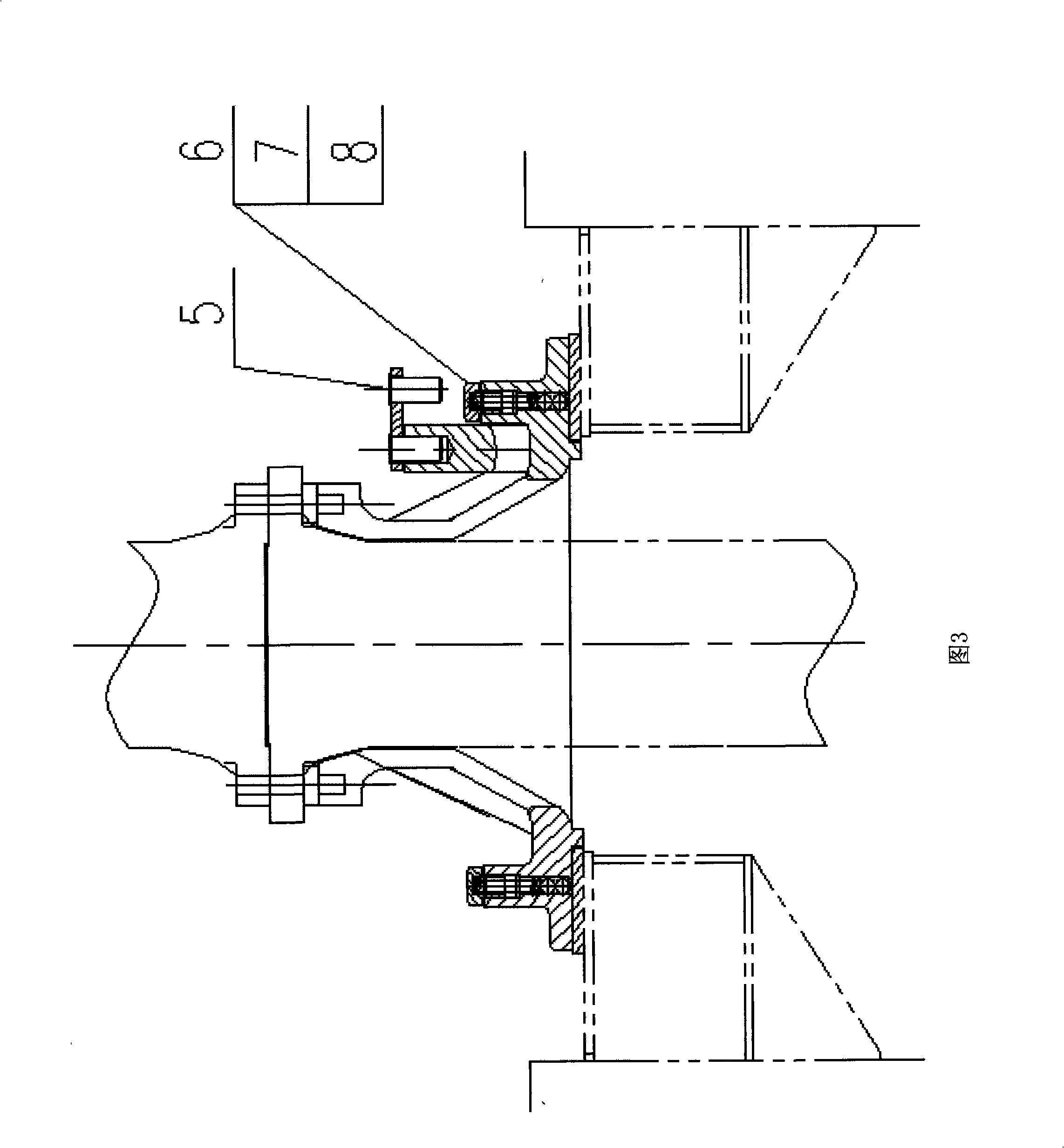
[0020] As shown in Figures 1 and 2: the clamping device used for connecting and unloading drill pipes of the present invention mainly consists of a support (1), an oil cylinder (2), a half clamping clamp (3), a bushing (4), a bolt ( 6), spring (7), steel ball (8), wherein the support (1) is fixed on the external reserved platform (10), one end of the oil cylinder (2) is connected with the support (1), and the other end is connected with the half-holding card ( 3) Connection, the semi-embracing card (3) is placed on the external reserved platform (10); the structural composition of the connected support (1), oil cylinder (2), and half-embracing card (3) is symmetrical along the axis of the oil cylinder (2) card holding device. The half-holding card (3) is designed as a special-shaped structure with a small top and a large bottom. The upper part is in the shape of a semicircular cylinder, and the lower part is a combination of a semicircular cone and a large-area flat plate; the...


PUM


Abstract

Disclosed is a hold-clamp device for the mounting and demounting of the drill rod, comprising a support (1), an oil cylinder (2), a semi hold-clamp (3), a liner (4), a bolt (6), a spring (7) and a steel ball (8); wherein, the support is fixed on an external reserved platform (10); one end of the oil cylinder is connected with the support and the other end is connected with the semi hold-clamp which is mounted on the external reserved platform; the support, the oil cylinder and the semi hold-clamp are connected together to form the hold-clamp device which is symmetrical along the axial line of the oil cylinder; the semi hold-clamp is designed to a special structure which has a small upper part and a big lower part; the upper part is shaped like a semicircular cylinder; the lower part is shaped like that a semicircular cone which is joint with a flat plate with large area; a lug boss is arranged on the top of the semicircular cylinder; the liner can be arranged on the position of the lug boss; an inner hole and a pin shaft hole are arranged on both sides of the lower part flat plate shaped position; the steel ball, the spring and the bolt are arranged in the inner hole. The hold-clamp device has the advantages of compact structure, reliable application, not only being used for mounting and demounting the flange drill rod, but also being used for mounting and demounting the embedded tooth drill rod, good generality and improving the work efficiency greatly.

Description

technical field [0001] The invention belongs to the technical field of shaft drilling machines, in particular to a clamping device for connecting and unloading drill pipes. Background technique [0002] During engineering construction, the drill pipes of the shaft drilling rig are connected by tens or hundreds of pieces, reaching a depth of hundreds or even kilometers. [0003] In shaft drilling rigs, the mechanism used to hold the drill pipe on the drill floor car is bulky, heavy, and cumbersome to operate. With the advancement of technology and the improvement of the structure of the drilling rig, the original equipment seriously affects the improvement of the structure of the drilling rig, which restricts the reduction of the space and compact structure of the drilling rig, which in turn affects the reduction of cost and simplification of operation. [0004] In the past, the engagement mechanism of shaft drilling rigs was mostly driven by cylinders, and the engagement me...

Claims


Application Information

Patent Timeline
Patent Type & Authority Applications(China)
IPC IPC(8): E21B19/10
Inventor 金汝励苗军克李客
Owner CITIC HEAVY INDUSTRIES CO LTD
Why Eureka
Try Eureka