
Device of engine for continuously changing air valve phase

A phase device, engine technology, applied in engine components, engine control, combustion engine, etc., can solve the problems of complex structure, inconvenient valve clearance adjustment, loud noise, etc., and achieve the effect of simple structure

Inactive Publication Date: 2008-12-31
李建春
View PDF0 Cites 6 Cited by
  • Summary
  • Abstract
  • Description
  • Claims
  • Application Information

AI Technical Summary

Problems solved by technology

However, although the three-dimensional cam solution of Fiat Company solves the continuously adjustable change of valve phase, it adopts the method of axially moving the camshaft to realize it, so there are two defects: one defect is that the axially moving three-dimensional cam and the drive chain Wheels or gears can only be connected by dynamic fit, resulting in a more complex structure and greater noise; another defect is that it is very inconvenient to adjust the clearance of the valve during assembly

Method used


Image

  • Device of engine for continuously changing air valve phase

Examples


Embodiment Construction

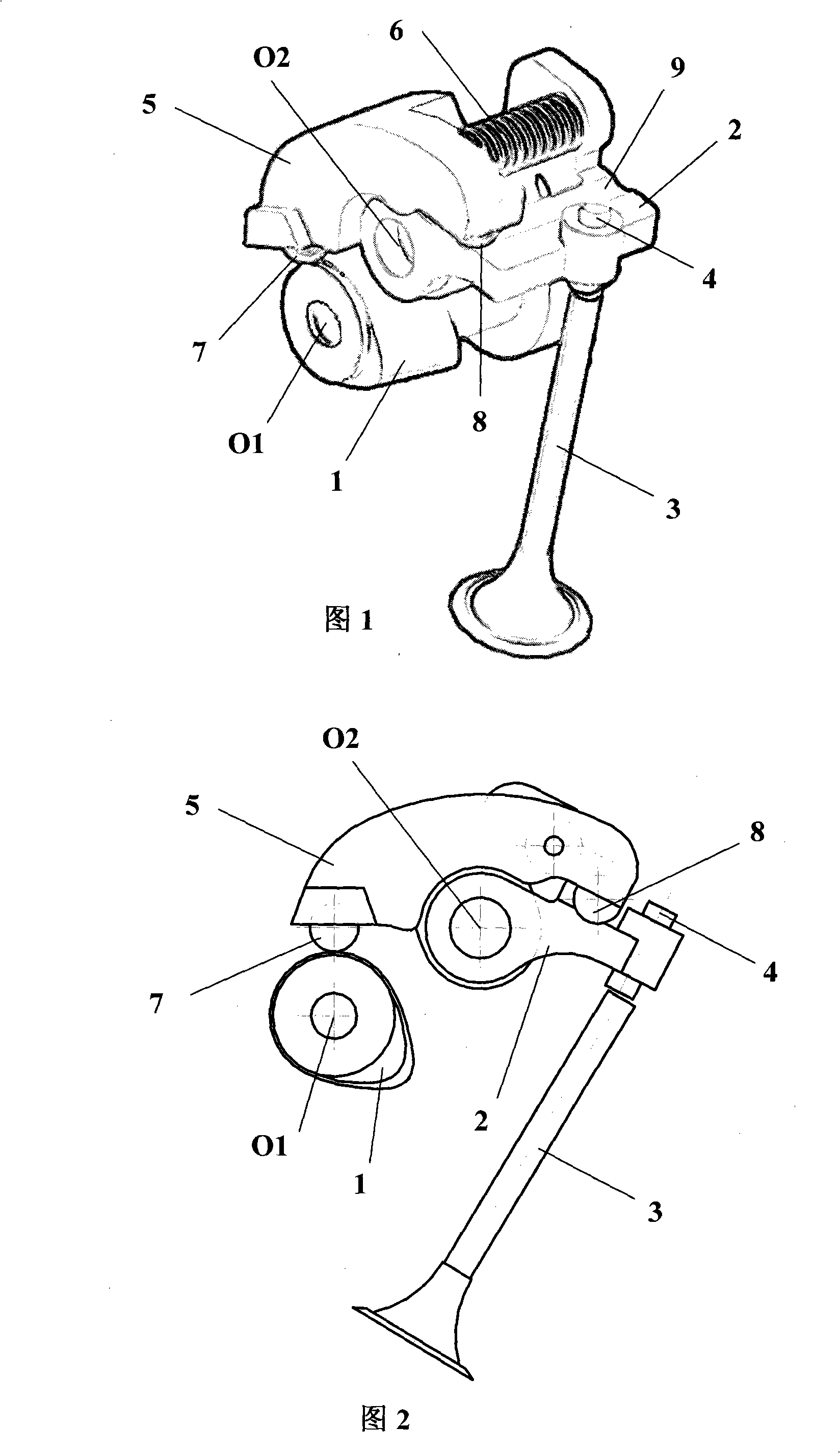
[0008] Fig. 1 and Fig. 2 respectively show a three-dimensional structure schematic diagram and a cross-sectional schematic diagram of an embodiment of a continuously variable valve phase device for an engine according to the present invention. In this embodiment, the device includes a three-dimensional cam 1, a main rocker arm 2, a valve 3 and a valve clearance adjustment screw 4; the three-dimensional cam 1 rotates around its axis O1, and the profile of the cross section of the three-dimensional cam 1 is The axial direction of the camshaft changes continuously and smoothly and corresponds to different working conditions of the engine; the main rocker arm 2 only rotates around its axis O2 without axial movement, and the valve clearance adjustment screw 4 is arranged on the main rocker arm 2; What is different from the previous valve driving mechanism is that in this embodiment, an auxiliary rocker arm 5 is arranged between the three-dimensional cam 1 and the main rocker arm 2, ...


PUM


Abstract

The invention provides a continually-variable air valve phase device which comprises a three-dimensional cam [1], a main rocker arm [2], an air valve [3], an air valve gap adjusting screw [4] and an auxiliary rocker arm [5]; the three-dimensional cam [1] can change the lift and the opening-closing time according to the practical operating condition of the engine; the outline line of the cross section of the three-dimensional cam [1] changes along the axial direction of the of the camshaft continually and smoothly corresponding to the different operating conditions of the engine; the auxiliary rocker arm [5] can move axially, transfer the power and movement of the three-dimensional cam [1] to the main rocker arm [2] and drive the air valve [3] through the air valve gap adjusting screw [4]; because the three-dimensional cam [1] and the main rocker arm [2] are unable to move axially, the structures of the three-dimensional cam and the main rocker arm are very simple and facilitate the adjustment of the air valve gap.

Description

technical field [0001] The invention relates to an engine valve phase control device, in particular to an engine continuously variable valve phase device. Background technique [0002] The opening and closing timing of the intake and exhaust valves of the engine and the size of the opening passage have a great influence on the performance, and the most favorable valve movement timing and passage area vary with the working conditions of the engine. The motion timing and valve lift of the traditional valve drive mechanism are fixed. Although it can guarantee the best performance of the engine in a certain working condition, such as the design working condition, it cannot fully take into account other working conditions. Obviously disadvantageous for frequent motor vehicle engines. Therefore, people have explored the variable valve phase drive technology, and put forward some implementation schemes, such as the intake camshaft valve phase control system (VTC) of the German KSA...

Claims


Application Information

Patent Timeline
IPC IPC(8): F02D13/02F01L13/00F01L1/18
CPCY02T10/12
Inventor 李建春耿爱农王大承
Owner 李建春
Learn More