
Elastic support installation method for wind power plant and its elastic element

A technology of wind power generation equipment and elastic support, applied in the field of vibration isolation connection and gearbox support, to achieve the effect of safe installation process, small structure and compact structure

Inactive Publication Date: 2008-12-31
ZHUZHOU TIMES NEW MATERIALS TECH
View PDF1 Cites 21 Cited by
  • Summary
  • Abstract
  • Description
  • Claims
  • Application Information

AI Technical Summary

Problems solved by technology

[0004] The purpose of the present invention is to propose an installation method that can improve the installation conditions of the elastic support for the gearbox of the wind turbine for the deficiencies in the elastic support of the gearbox of the existing wind turbine.

Method used


Image

  • Elastic support installation method for wind power plant and its elastic element
  • Elastic support installation method for wind power plant and its elastic element
  • Elastic support installation method for wind power plant and its elastic element

Examples


Embodiment 1

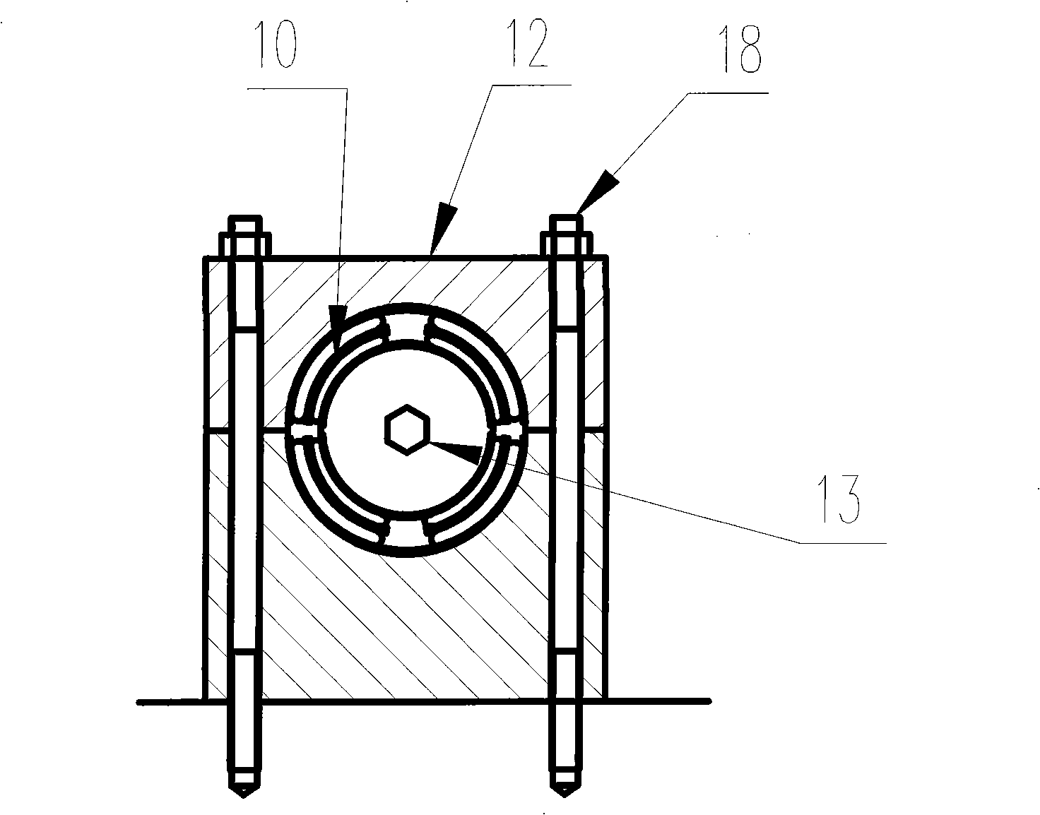
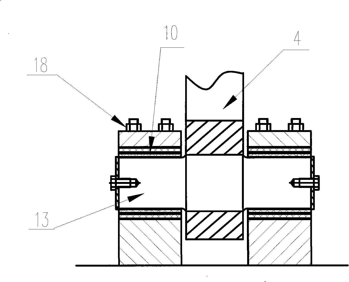
[0020] attached figure 2 And attached image 3 It shows a method for installing the elastic support of the gearbox of a wind power generating set according to the present invention. The elastic support 10 of the gearbox of the wind generating set is installed on the gearbox 11 of the wind generating set. The elastic support of the two-lobed structure is adopted, and the elastic support 10 is installed on the gear On both sides of the box 11, and through the support 12 of the upper and lower halves, the elastic support is installed in the support 12 by means of radial pre-tightening compression, forming an elastic support for the wind turbine gearbox. The radial pre-tightening compression method is as follows: first place the two elastic supports 10 in the upper and lower two halves of the support 12, and compress radially to make the outer ring of the elastic support 10 stick to the inner circle of the support 12. Together, the mandrel 13 is placed on the inner ring of the e...

Embodiment 2

[0023] Image 6 It shows another installation method for the elastic support of the gearbox of the wind power generating set, adopting the elastic support 210 in the form of integral structure, installing the elastic support 210 on both sides of the gearbox 211, and the support 212 is the support of the integral structure, adopting radial The elastic support 210 is installed in the support 211 in a tight compression method to form an elastic support for the gearbox of the wind power generating set. The radial pre-tightening compression method is to put the inner ring of the elastic support 210 on the mandrel 213, then radially compress the outer ring and place it in the support, so that the elastic support 210 generates a certain pre-compression force and installs it on the support. 212 inside. The implementation of radial compression refers to the use of a special compression tool to radially compress the outer tile of the elastic support 210 from the outer tile or the end t...


PUM


Abstract

The invention relates to an elastic support installation method and an elastic element thereof used for a wind power generation equipment. Elastic supports are installed at both sides of a gearbox and installed in a supporting seat by adopting a radial pretension compression method to form the elastic support for the gearbox of a wind driven generating unit. The elastic support installation method adopts the radial pretension compression method that the elastic supports are arranged in the supporting seat after being radially compressed through a special compression tool or directly utilizing the supporting seat in order to tightly embrace a core axle and to generate a certain pre-compression force. The gearbox elastic support of the wind driven generating unit comprises an elastic body, an outer tile and an inner tile, wherein, the outer tile adopts a multiple-flap arc structure of more than two flaps, the elastic body adopts at least more than one layer, the elastic support adopts an integral structure or a split type combined structure, each outer tile adopts a concentric circular arc with respect to the inner tile under the initial state, and variable radius structures with unequal radiuses are adopted among the outer tile, the inner tile, the core axle and the supporting seat.

Description

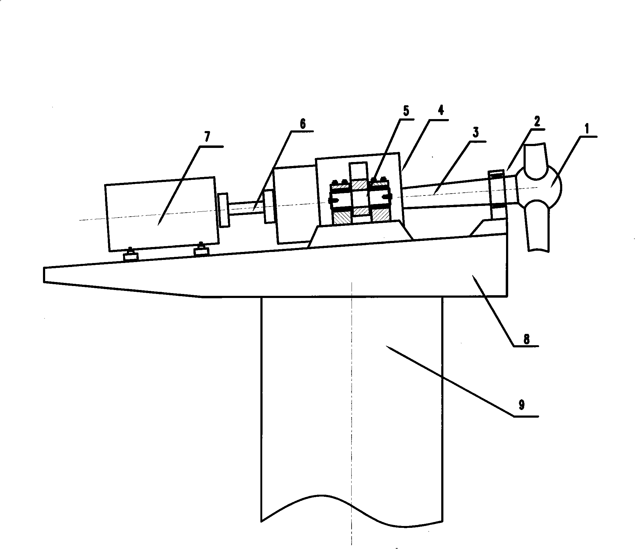
technical field [0001] The invention mainly relates to a support device for wind power generating set equipment, in particular to an elastic support applied to the vibration reduction of wind power generating set equipment, and mainly applied to the gear box support of the wind power generating set transmission system. The invention is also applicable to the vibration isolation connection of vehicles, ships, construction machinery and other equipment. Background technique [0002] The wind turbine transmission system is mainly supported by 3 points, such as figure 1 As shown, the first point of support is the main bearing 2, which is located between the fan impeller 1 and the main shaft 3; the second point of support is the gearbox support 5, which is located on the gearbox 4; the third point of support is the support of the motor 7, and the motor passes through The coupling 6 is connected with the gearbox 4 . Three points of support are all installed on the main frame 8, ...

Claims


Application Information

Patent Timeline
Patent Type & Authority Applications(China)
IPC IPC(8): F03D1/00F03D11/04F16C17/00F16C35/02F16H57/00F03D13/10F16H57/025
CPCY02E10/72
Inventor 林胜张亚新唐先贺胡伟辉周宏惠秦中正
Owner ZHUZHOU TIMES NEW MATERIALS TECH
Learn More