
Power protection apparatus and electronic control unit

A technology of power protection and power supply, which is applied in the direction of emergency protection circuit devices, measuring devices, electronic switches, etc., and can solve problems such as disconnection, high price, failure of the MOS-FET diode coil 130 of the switching circuit 400, etc.

Inactive Publication Date: 2008-12-31
FUJITSU GENERAL LTD
View PDF1 Cites 43 Cited by
  • Summary
  • Abstract
  • Description
  • Claims
  • Application Information

AI Technical Summary

Problems solved by technology

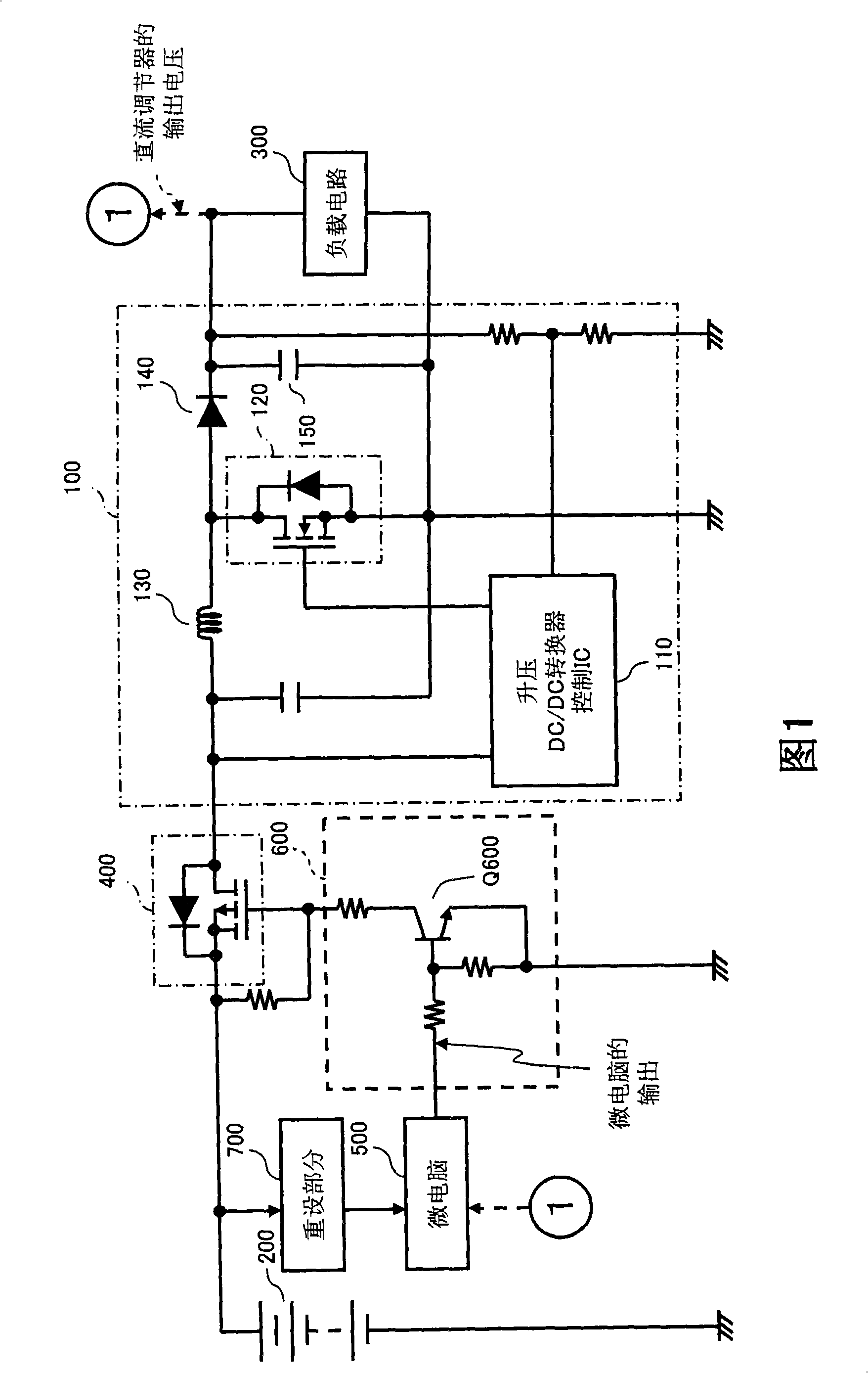
[0003] Such a circuit structure has the following problem: when an abnormality such as a short circuit occurs in the DC regulator 100 or the load circuit 300, an unexpected excessive current flows from the power supply 200 into the DC regulator 100 and the load circuit 300, so that the switch circuit 400 is formed. MOS-FET, diode 140, coil 130, etc. may fail, and the switch circuit 400 switches whether to supply power from the power supply 200 to the load circuit 300
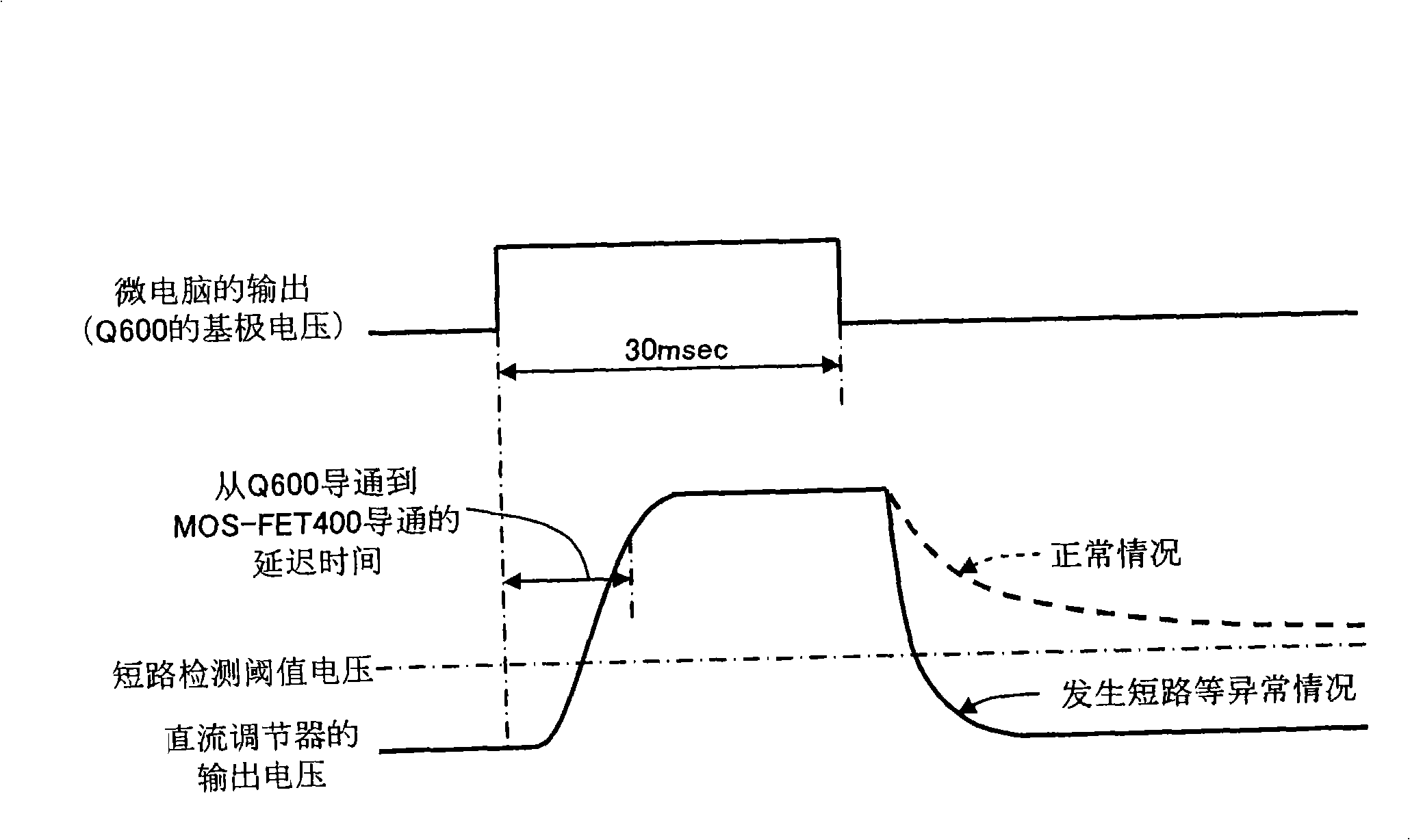
[0013] That is to say, there is a problem that the switch circuit 400 is repeatedly turned on and off, and the overcurrent flowing during this period may destroy elements such as the switch circuit 400, the diode 140, and the coil 130.
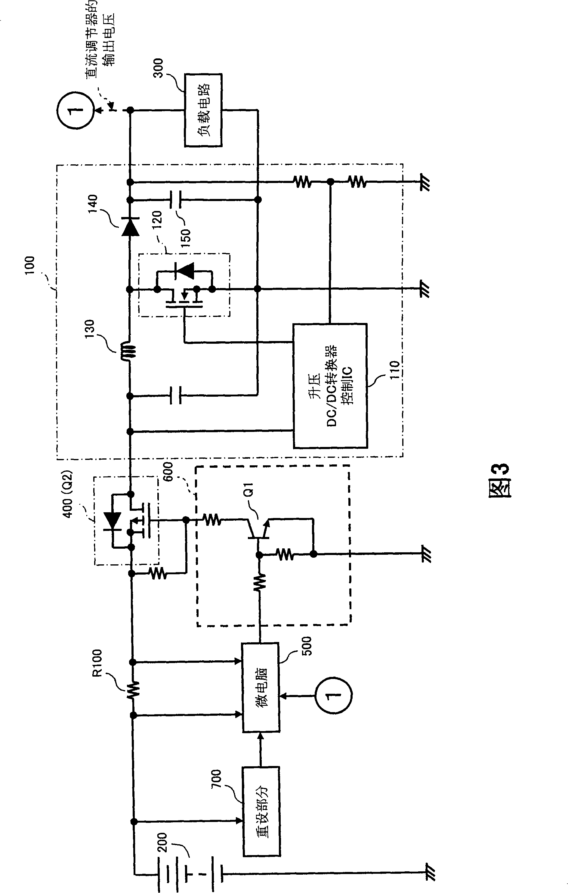
[0016] However, in order to ensure accurate and early detection of an overcurrent due to a short circuit based on the voltage across the resistor R100, high-speed sampling is required, so there is a problem that an expensive and high-performance microcomputer 500 is required

Method used


Image

  • Power protection apparatus and electronic control unit
  • Power protection apparatus and electronic control unit
  • Power protection apparatus and electronic control unit

Examples


Embodiment Construction

[0037] Hereinafter, the power protection device and electronic control device of the present invention will be described.

[0038] In this embodiment, the case where a power supply protection device is built into an electronic control device mounted on a vehicle is described as an example. The electronic control device has a CPU (Central Processor Unit, central processing unit) and a memory for storing control information of the CPU. This CPU functions as a display controller and controls a liquid crystal module connected to a DC regulator as a load.

[0039] As shown in Figure 4, the power protection device 1 has a switch part 4, a first short-circuit detection part 5, a reset part 6, a second short-circuit detection part 7 and a switch disconnection part 8, and the switch part 4 has The formed DC14V power supply 2 supplies power to the MOS-FET 41 on the power supply line of the DC regulator 3; the first short-circuit detection part 5 has a CPU, and the CPU makes the switch p...


PUM


Abstract

A power protection apparatus including: a switch unit (4) connected in series in a power supply line from a power source (2) to a DC regulator (3); a first short-circuit detector (5) for detecting a short circuit based on an output voltage value of the DC regulator (3) obtained by making the switch unit (4) conductive for predetermined time and, after that, interrupting the switch unit (4); a second short-circuit detector (7) for detecting a short circuit based on a value of current flowing in the switch unit (4) when the switch unit (4) is conductive; and a switch interrupting unit (8), when a short circuit is detected by the second short-circuit detector (7), for forcedly interrupting the switch unit (4) regardless of a state of the switch unit (4) controlled by the first short-circuit detector (5).

Description

technical field [0001] The present invention relates to a power protection device and an electronic control device. The power protection device includes a switch part, a first short-circuit detection part and a reset part. The switch part is connected in series to a power supply line from a power supply to a DC regulator. The short-circuit detection part turns on the switch part for a specified time and then disconnects it, and detects the short circuit according to the output voltage value of the DC regulator after disconnection, and resets the action of the first short-circuit detection part when the output voltage of the power supply drops to a specified voltage. to reset. Background technique [0002] As shown in FIG. 1 , the structure of a DC regulator 100 composed of a step-up DC / DC (direct current / direct current) converter is: using a step-up DC / DC converter control IC (Integrated Circuit, integrated circuit) 110 to MOS- FET (Metal Oxide Semiconductor Field Effect Tr...

Claims


Application Information

Patent Timeline
IPC IPC(8): H02H7/122G01R31/02
CPCH02H7/1213H03K17/08122H03K17/08142H03K17/0822H03K17/30
Inventor 松本敏浩佃浩司
Owner FUJITSU GENERAL LTD
Learn More