Automatic manufacturing device for spiral tube and producing method

An automatic production and driving device technology, applied in glass production, glass molding, glass reshaping, etc., can solve problems such as inability to guarantee the quality of lamp tube production, unstable lamp quality, and difficult to accurately control time

Inactive Publication Date: 2009-01-07
陈伯川
View PDF2 Cites 11 Cited by
  • Summary
  • Abstract
  • Description
  • Claims
  • Application Information

AI Technical Summary

Problems solved by technology

In this process, the operator is working in a heated environment, especially in summer, the working environment is harsh, which has a great impact on the health of the operator. Moreover, each process of bending the tube is completed manually, starting from the raw material of the lamp tube. In the process of bending the tube, the time is difficult to control accurately, which will cause the quality of the bent tube to be unstable
[0004] Patent No. "200710068040.X" titled "Pipe Bending Device for Energy-saving Lamp Tube Bending Machine" discloses a device that can control the two ends of the lamp tube to move toward the middle during the lamp tube bending process, but the patent still It does not get rid of...

Method used


Image

  • Automatic manufacturing device for spiral tube and producing method

Examples


Embodiment 1

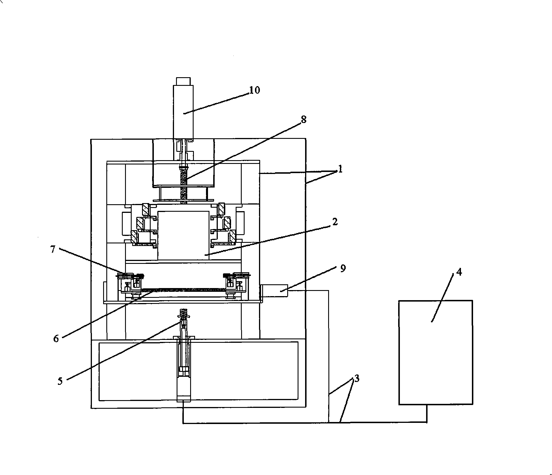
[0070] Such as figure 1 As shown, the automatic production device for spiral lamp tubes in this embodiment includes a frame 1 and a heating furnace 2 installed on the frame, an air-filled claw 7, and a spiral tube mold 5. The outer surface of the spiral tube mold is provided with a spiral groove, and through the automatic The rotating and lifting device is connected with the frame, and the inflatable claw is connected with the frame 1 through the horizontal lead screw 6 and the longitudinal lead screw 8. The automatic production device also includes a control device, which is composed of a console 4, a control circuit 3 and a driving device. The console 4 is connected to the driving device through the control line 3, and the driving device controls the actions of the inflatable claw 7 and the rotary tube mold 5 to be connected with each other when processing the lamp tube. The control device can realize numerical control automation in the production of lamp tubes, and achieve ...


PUM


Abstract

The invention relates to an automatic production device and a production method of a spiral lamp tube. The automatic production device comprises a machine frame, as well as a heating furnace, an inflated claw and a coil pipe mould which are mounted on the machine frame; a spiral groove is arranged on the outer surface of the coil pipe mould, and can rotate and lift relatively to the machine frame; and the inflated claw is connected with the machine frame through a transversal movement mechanism and a longitudinal movement mechanism. The automatic production device further comprises a control device; the control device is composed of a console, a control circuit and a drive device; the console is connected with the drive device through the control circuit; the drive device controls the action of the inflated claw and the coil pipe mould to be mutually connected during the manufacturing process of the lamp tube. The automatic production device can ensure that the production of the lamp tube realizes numerical control automation, so that the temperature, the speed, the position and other parameters during the production process achieve fine control, and an operator can be far away from the operating environment with high temperature.

Description

technical field [0001] The invention relates to a manufacturing mechanical device of an energy-saving lamp tube and a production method thereof, in particular to a manufacturing mechanical device of a spiral energy-saving lamp tube and a production method thereof. Background technique [0002] In recent years, energy-saving lamps have appeared in the lighting market. Compared with the previous incandescent lamps, energy-saving lamps have many advantages: 1. High luminous efficiency. Luminous efficiency is the luminous efficiency, which refers to the ratio of the luminous flux emitted by a light source to the electrical power consumed. It can be expressed in lumens per watt or LM / W (luminous flux: refers to the amount of light emitted by the light source per unit time, it is an important indicator to measure the brightness of the lamp, expressed in LM.) Compared with ordinary bulbs, energy-saving lamps emit more light The efficiency is increased by about 5-6 times. For examp...

Claims


Application Information

Patent Timeline
IPC IPC(8): C03B23/045C03B23/06H01J9/24
CPCY02P40/57
Inventor 陈伯川
Owner 陈伯川
Why Eureka
Try Eureka