Optical diffusion thin film and LCD device using the optical diffusion thin film

A liquid crystal display device and optical diffusion technology, applied in the field of optical diffusion film and liquid crystal display device, can solve the problems of reduced brightness gain, low brightness, large gap, etc., achieve high optical uniformity and brightness, reduce light source loss, The effect of reducing the number of combined components

Active Publication Date: 2009-01-07
NINGBO EXCITON TECH
View PDF0 Cites 5 Cited by
  • Summary
  • Abstract
  • Description
  • Claims
  • Application Information

AI Technical Summary

Problems solved by technology

However, in this design, since only a few particles with larger sizes protrude from the coating, and because the particle diameters of these larger particles are larger, the gap between the particles is larger, causing part of the light source to pass through the gap. Leaked, resulting in loss of light source, so the light gathering ability of this film is very limited
Moreover, the shape and size distribution of the particles is very wide. Although the optical diffusion ability of the film can be increased, the light-gathering ability of the film is lost at the same time, and the brightness gain is reduced, so that the brightness of the liquid crystal display device directly using this film is not high.

Method used


Image

  • Optical diffusion thin film and LCD device using the optical diffusion thin film
  • Optical diffusion thin film and LCD device using the optical diffusion thin film
  • Optical diffusion thin film and LCD device using the optical diffusion thin film

Examples


Embodiment 1

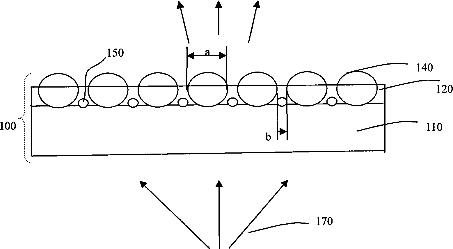
[0023] Such as figure 1 As shown, an optical diffusion film, the optical diffusion film 100 mainly includes a transparent substrate 110, the upper surface of the transparent substrate 110 is provided with an upper diffusion coating 120, the upper diffusion coating 120 is provided with upper diffusion particles, and the upper diffusion coating 120 is provided with upper diffusion particles. The diffusion particles are distributed on the upper surface of the transparent substrate 110 , and the upper diffusion particles include large particles 140 with a spherical structure and small particles 150 with a spherical structure. In this specific embodiment, the maximum geometric dimension of the large particle 140 can be in the range of 1-100 microns. When the large particle 140 is larger, that is, when the maximum geometric dimension is greater than 100 microns, the coating process will be more difficult, and when the large particle 140 is larger than 100 microns, the coating proces...

Embodiment 2

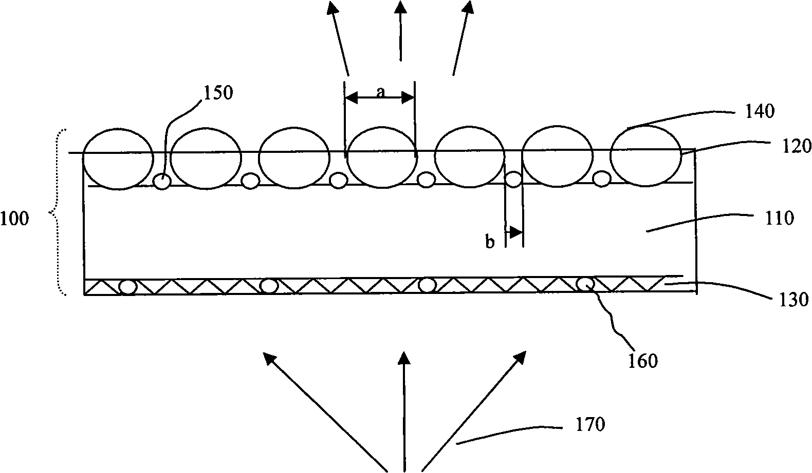
[0027] Such as figure 2 As shown, the structure of this embodiment is basically the same as that of Embodiment 1, the only difference is that an anti-adhesive coating 130 with a textured structure is provided on the lower surface of the transparent substrate 110 of this embodiment, and the anti-adhesive coating Spherical anti-adhesion particles 160 are arranged inside 130 , and the particle size of the anti-adhesion particles 160 is slightly larger than the thickness of the anti-adhesion coating 130 after film formation. The geometric size of the anti-adhesion particles 160 is relatively small, and in this embodiment the particle diameter of the anti-adhesion particles is about 5 microns, and they are arranged on the lower surface of the transparent substrate 110 by randomly scattered and sparsely non-contact, so that the optical When the diffusion film 100 is specifically applied in a backlight module, a thin air layer is formed between other components. The ratio of the su...

Embodiment 3

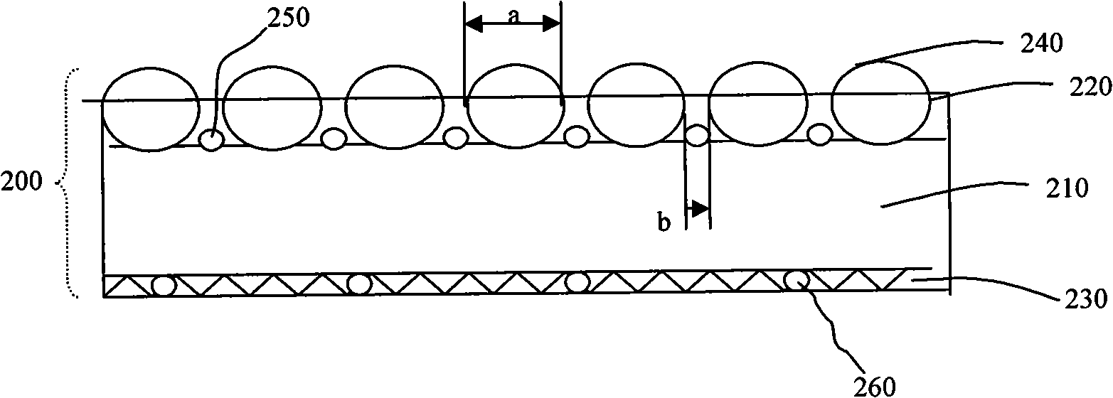
[0029] Such as image 3As shown, the optical diffusion film 200 of this embodiment also includes a transparent substrate 210, an upper diffusion coating 220 containing large spherical particles 240 and small spherical particles 250, and an anti-adhesive particle 260 with a textured structure. Anti-stick coating 230. and figure 2 The difference of the shown embodiment two is that the particle diameter of the large particle 240 in this embodiment is 10 microns, the particle diameter of the small particle 250 is 5 microns, and the particle diameter ratio of the large particle 240 and the small particle 250 is 2:1 , this optical diffusion film 200 (mixed use of large and small particles) is compared with the optical diffusion film using large particles (particle diameter is 10 microns) for haze and brightness. As can be seen from Table 1, the optical diffusion film of the present embodiment The film 200 can change the atomization effect of the upper diffusion coating 220 and in...


PUM

PropertyMeasurementUnit
Sizeaaaaaaaaaa
Sizeaaaaaaaaaa

Abstract

The invention discloses an optical diffusion film and a liquid crystal display device using the optical diffusion film. The film comprises a transparent base plate, an upper diffusion coating provided with upper diffusion particles is arranged on the upper surface of the transparent base plate; wherein, the upper diffusion particles comprise macro-particles and micro-particles, and the maximum physical dimensions of the macro-particles and the micro-particles are respectively 1 - 100 microns and 0.1 - 50 microns; the physical dimension ratio of the macro-particles and the micro-particles parallel to the surface direction of the transparent base plate is 2:1 - 100:1, and the macro-particles and the micro-particles are arrayed at intervals; the thickness of the upper diffusion coating after film forming is 1 / 2 - 7 / 8 of the maximum physical dimension of the macro-particles. The optical diffusion film has the advantages that, by controlling the dimensions and shapes of the macro-particles and the micro-particles and arraying the macro-particles and the micro-particles at intervals, gaps between the macro-particles are replaced by the micro-particles, thus reducing the loss of light source, strengthening the condensation performance of the film, and achieving a favorable atomization effect. A display device adopting the film provided by the invention has the advantages of smaller quantity of combined components and higher optical uniformity and brightness.

Description

technical field [0001] The invention relates to an optical film, in particular to an optical diffusion film and a liquid crystal display device using the optical diffusion film. Background technique [0002] Existing optical diffusion films are widely used in devices requiring light sources such as liquid crystal display devices, advertising light boxes, lighting fixtures, and keys of mobile communication equipment to provide uniform illumination. In recent years, with the rapid development of liquid crystal display devices and their wide application in mobile communication equipment displays, notebook computer monitors, desktop computer monitors and large-size LCD TVs, the performance requirements for optical diffusion films used in liquid crystal display devices are also increasing. Improvement, mainly focused on improving brightness and lighting uniformity. [0003] The existing optical diffusion films used in liquid crystal display devices are mostly single-layer organi...

Claims


Application Information

Patent Timeline
IPC IPC(8): G02B5/02G02F1/13357G02F1/1335
Inventor 张彦金亚东
Owner NINGBO EXCITON TECH
Why Eureka
Try Eureka