
Bi-stable magnetic clutch

A magnetic clutch and bistable technology, applied in the field of clutches, can solve the problems of electromagnetic coils being easily damaged by heat, polluting the environment, and energy consumption, and achieve the effects of small electromagnetic pollution, wide application, and low energy consumption

Inactive Publication Date: 2009-01-07
刘新广
View PDF0 Cites 4 Cited by
  • Summary
  • Abstract
  • Description
  • Claims
  • Application Information

AI Technical Summary

Problems solved by technology

However, when the existing electromagnetic clutch is in the engaged state, its coil must be kept energized, so it consumes energy, and some also continue to energize through brushes and collector rings, which consumes energy to generate heat and magnetism, pollutes the environment, and its electromagnetic coil is easily heated. damage

Method used


Image

  • Bi-stable magnetic clutch
  • Bi-stable magnetic clutch
  • Bi-stable magnetic clutch

Examples


Embodiment 1

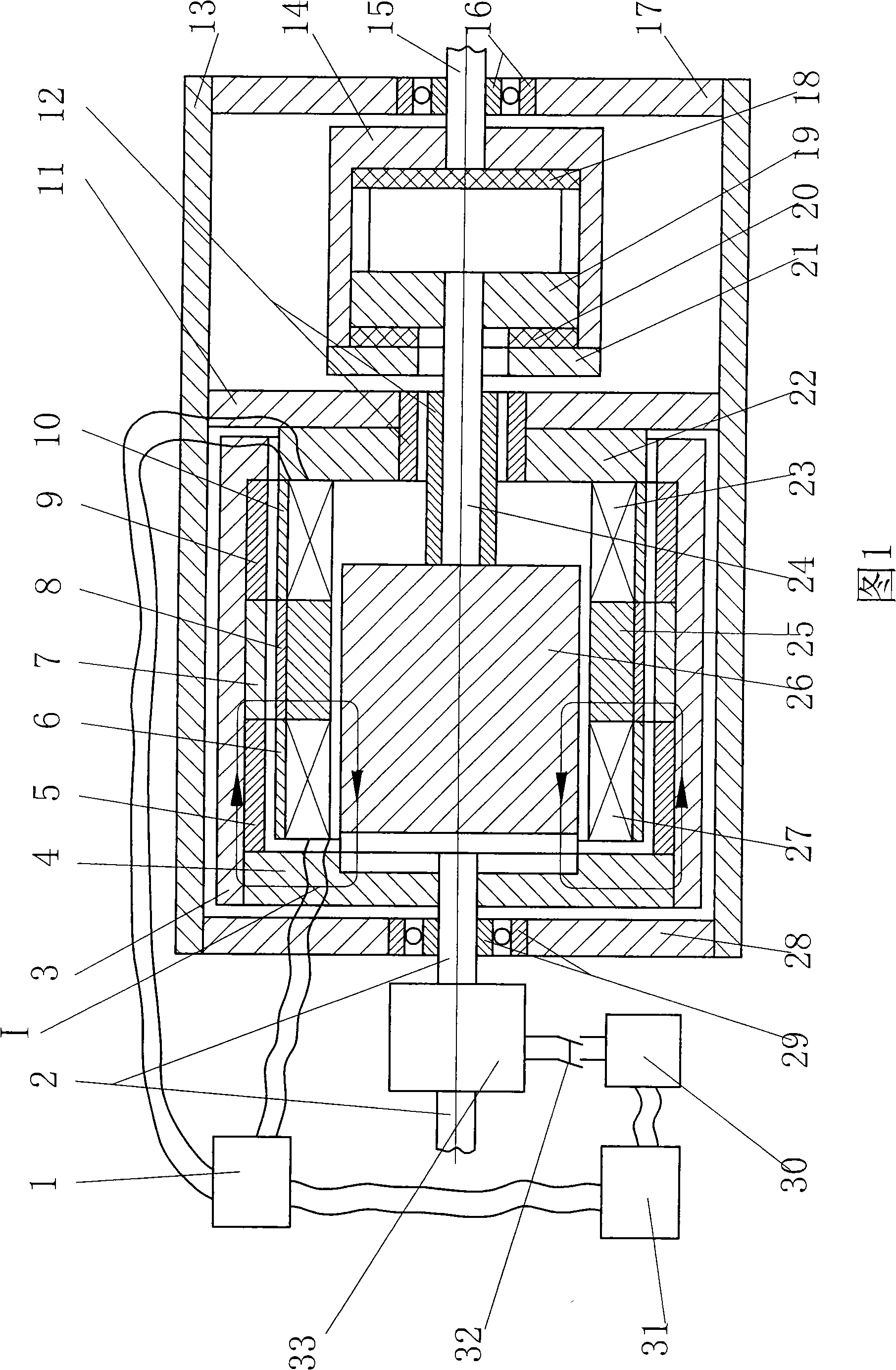
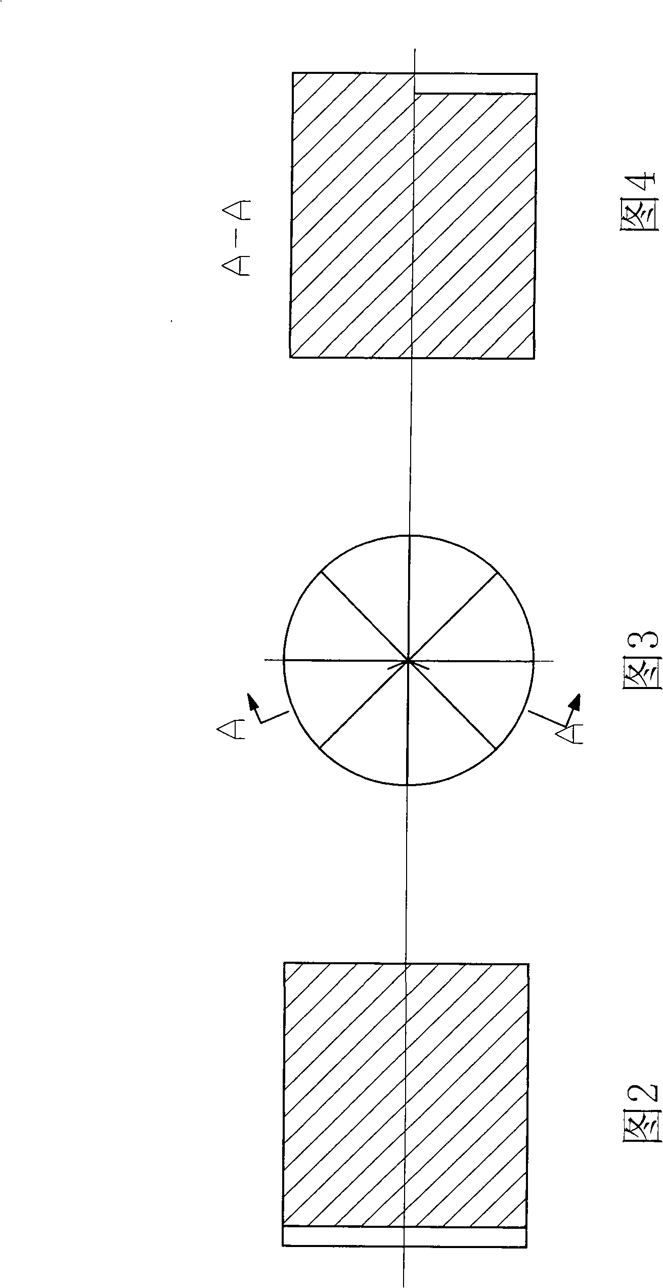
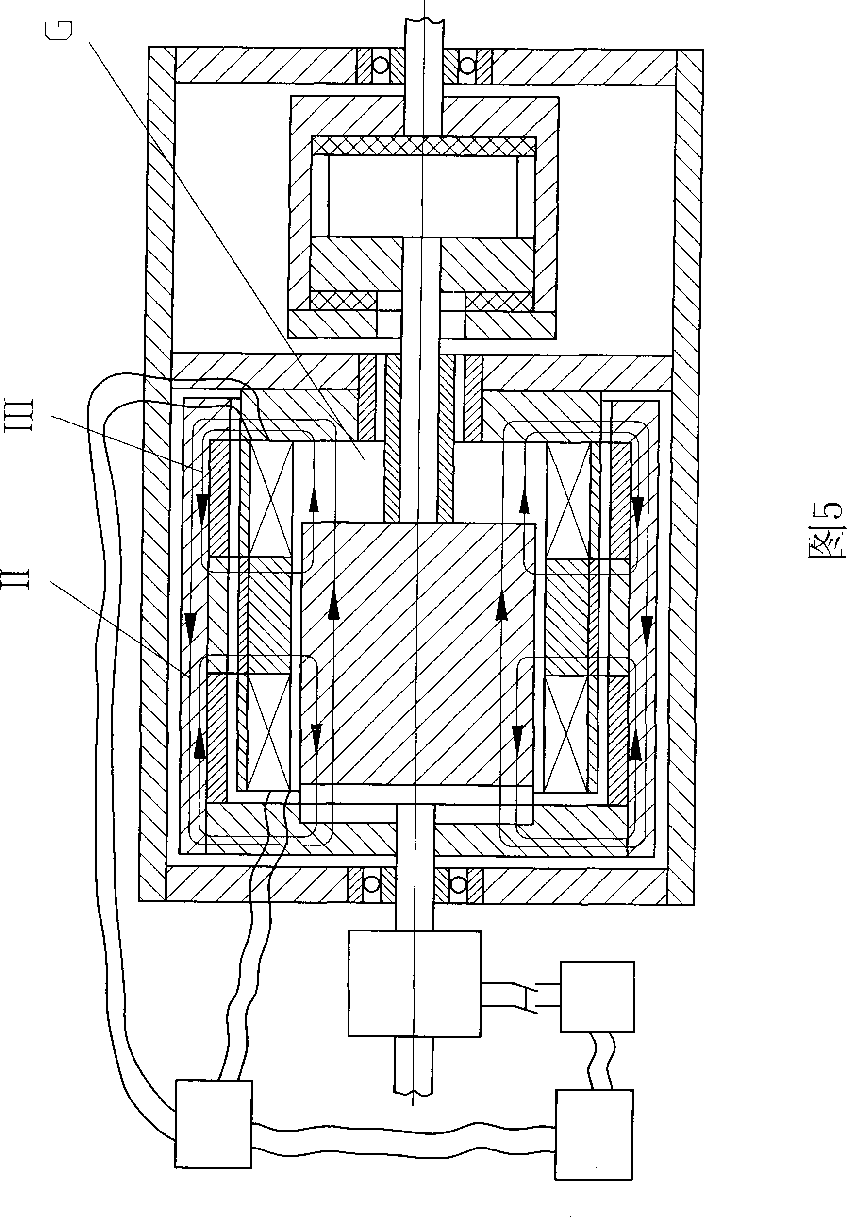
[0026] Embodiment 1: as shown in Figure 1 to Figure 4. The invention is composed of a driving wheel, a driven wheel, a stator, a brake and a control system. The driving wheel is made up of a magnet core 26, a spline stub 19, an inner spline sleeve 14 slidingly fitted with the spline stub 19, a buffer pad 18 and 20, an end plate 21, a drive shaft 15 and a shaft 24, and the magnet guide The core 26 and the spline short column 19 are coaxially consolidated with the shaft 24, the left end surface of the magnetic conductor core 26 is evenly distributed with fan-shaped teeth, the buffer pads 18 and 20 and the end plate 21 are connected with the inner spline sleeve 14, and the inner spline sleeve The cylinder 14 is connected with the drive shaft 15 and consolidated; the driven wheel is formed by the consolidation of the driven shaft 2, the magnetic conduction cylinder 3, the conduction disc 4, the non-magnetic rings 5 ​​and 9 and the radially magnetized permanent magnet ring 7, and t...

Embodiment 2

[0028] Embodiment 2: as shown in FIG. 7 . For the clutch described in embodiment one, the non-magnetic rings 5 ​​and 9 are removed, and the combination of the magnetic-conducting cylinder 3 and the permanent-magnetic ring 7 is changed into the magnetic-conducting cylinder 34. Its shape and size are the same as the former, and the others remain unchanged. Under the condition of meeting the performance requirements of the clutch, this can simplify the structure, reduce the cost, and improve the high temperature adaptability of the driven wheel. Fig. 7 is a schematic diagram of the combined state of this embodiment, and Fig. 8 is a schematic diagram of the detached state of this embodiment. The dotted lines V and VI in the figure show the path of the permanent magnetic flux.

Embodiment 3

[0029] Embodiment three: as shown in FIG. 9 . For the clutch described in Embodiment 1, only the permanent magnet ring 25 and the magnetic permeable ring 8 are changed to the magnetic permeable cylinder 35, which can simplify the structure, reduce the cost and improve the high temperature adaptability of the stator under the condition of meeting the performance requirements of the clutch. Fig. 9 is a schematic diagram of the combined state of this embodiment, and Fig. 10 is a schematic diagram of the detached state of this embodiment. The dotted lines VII and VIII in the figure are schematic diagrams of the paths of the permanent magnetic flux.


PUM


Abstract

The invention relates to a bistable magnetic clutch; wherein, a permanent magnet and an operating coil are arranged between a driving wheel and a driven wheel; a permanent magnetor type brake is arranged on the driven wheel; the clutch keeps subject to permanent magnetic force in the separating state and the bonding state, but the mutual shift between the separating state and the bonding state is realized on condition that the electromagnetic force of the operating coil overcomes permanent magnetic force to lead a permanent magnetic line to change direction. When the clutch shifts from the bonding state to the separating state, the brake brakes, that is, the stator coil of a permanent magnetor is bonded to form a closed-loop, and the permanent magnet rotor of a permanent magnetor rotating along the driven shaft leads the stator coil to generate an inductive magnetic field which stops the permanent rotor from rotating to realize the brake and generates external power simultaneously. The bistable magnetic clutch has the advantages of quick operation, environmental protection, little maintenance, and long service life, and being suitable for various working conditions on condition that a driven mechanism and a power source are bonded or separated.

Description

technical field [0001] The invention relates to clutch technology, in particular to a bistable magnetic clutch. Background technique [0002] The clutch is a device that cuts off and connects the driving source and the driven mechanism. Traditional clutches are mechanical and electromagnetic. The mechanical normally engaged clutch is separated by external mechanical force (hydraulic pressure is required for large clutches), and the engagement is achieved by pressing the friction plate by spring pressure, and the clutch process is long, so it is not suitable for automatic control engineering. During the clutching process of this clutch, the friction plates rub against each other to consume energy and generate heat, and the friction plates are easily damaged. The existing electromagnetic clutch is engaged by electromagnetic force and separated by pulling force of a separation spring, has high operating speed, can be used in automatic control engineering, and has no friction ...

Claims


Application Information

Patent Timeline
Patent Type & Authority Applications(China)
IPC IPC(8): H02K49/10
Inventor 刘新广
Owner 刘新广
Learn More