
Apparatus, method and system of thin client blade modularity

A thin client, modular technology, applied in the direction of support structure installation, multiple digital computer combinations, circuit layout on support structures, etc., can solve problems such as difficult simulation and unreliable simulation

Inactive Publication Date: 2009-01-07
CHIP PC ISRAEL LTD
View PDF6 Cites 9 Cited by
  • Summary
  • Abstract
  • Description
  • Claims
  • Application Information

AI Technical Summary

Problems solved by technology

[0014] Although in the case of thin client workstations there is an option to use multiple virtual (simulated) clients running on a single platform as simulated user workstations, the simulation will be less reliable than in the case of PC workstations since thin clients use a completely different architecture structure and is difficult to emulate under current virtual machine conditions

Method used


Image

  • Apparatus, method and system of thin client blade modularity
  • Apparatus, method and system of thin client blade modularity
  • Apparatus, method and system of thin client blade modularity

Examples


Embodiment Construction

[0050] The following detailed description is the best mode for implementing the present invention. The description should not be regarded as a limitation, but only for the purpose of illustrating the general principles according to the present invention. The scope of the present invention is determined by the appended claims.

[0051] Further reference will now be made to the drawings, in which exemplary embodiments of the present invention are shown.

[0052] The foregoing and other objectives, features, and advantages of the present invention will be apparent from the following more detailed description of exemplary embodiments of the present invention as shown in the drawings.

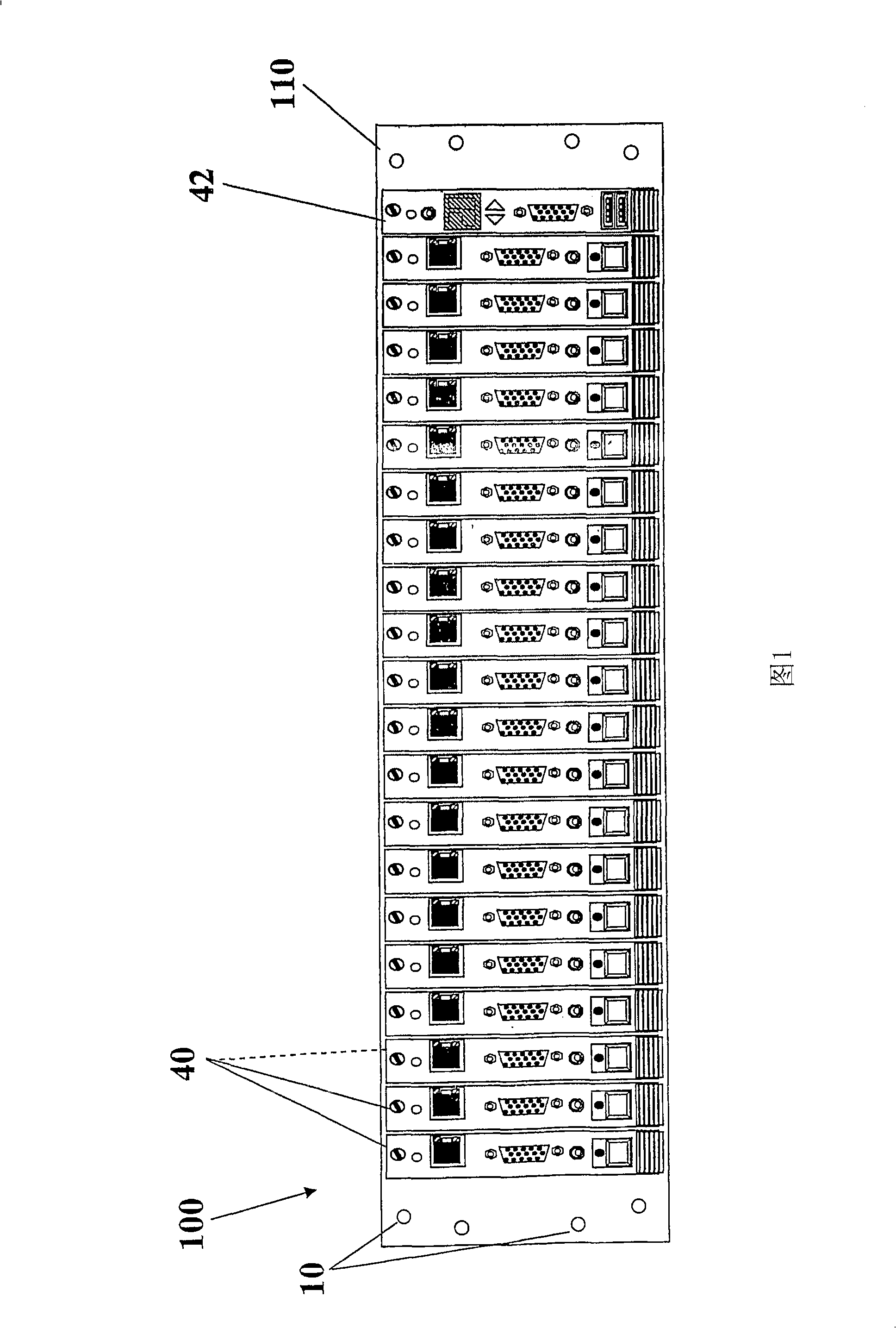
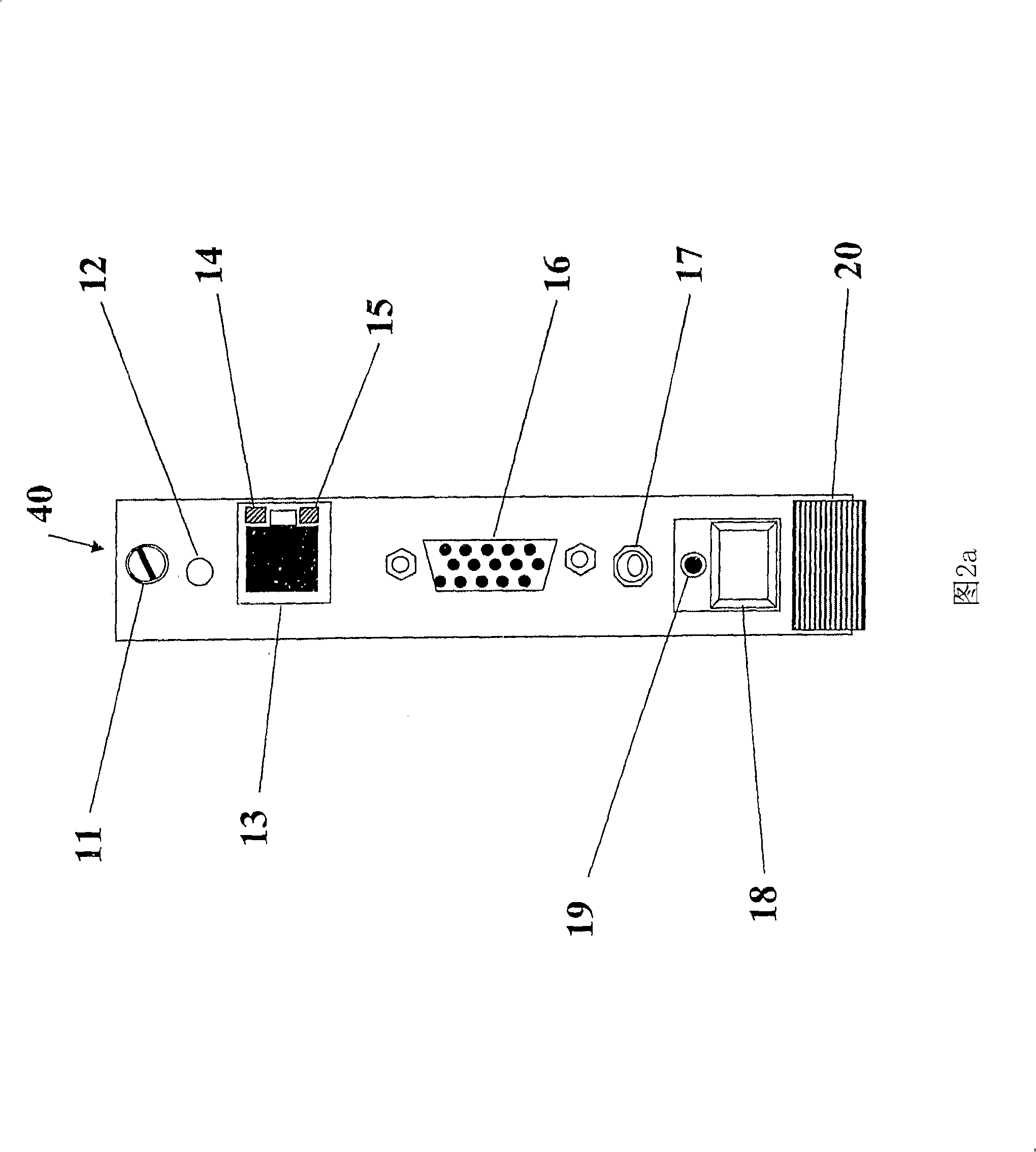
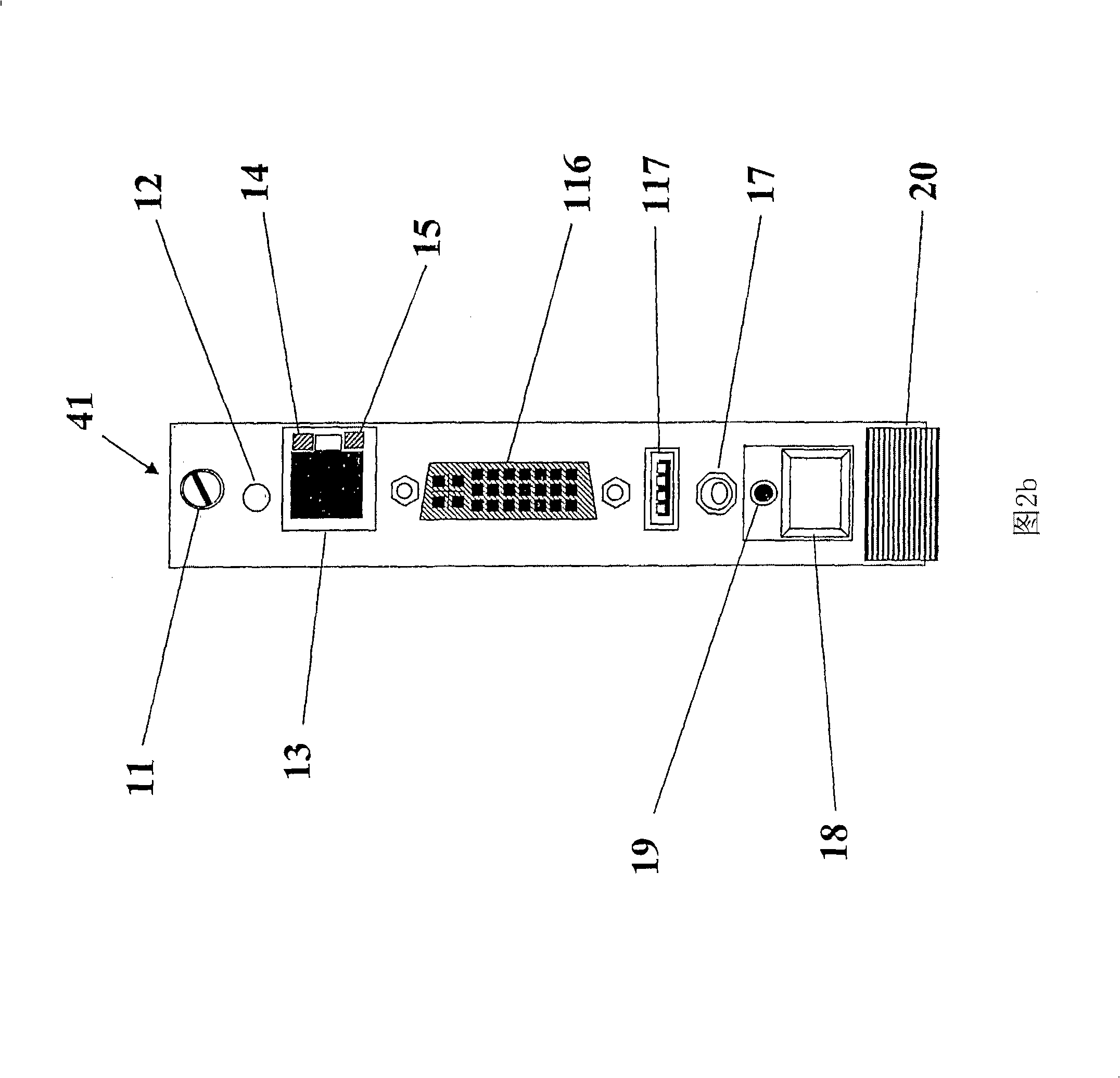
[0053] Referring to FIG. 1, there is shown a front view of an embodiment 100 of a thin client modular blade system. The bottom frame rack mounting holes 10 are used to fasten the bottom frame 110 to a standard rack. Generally, the standard 19" rack geometry is used to enable the vertical formation of mu...


PUM


Abstract

The present invention provides a modular chassis comprising multiple thin-client blades removeably connectable to a common midplane and to one or more power supplies and one or more management modules to simulate multiple thin-client operating with one or more computer networks. The invention enables building large-scale computer laboratory environments having many thin-client devices and possibly many simulated users, easily connected and managed to simulate large computer infrastructure. Also disclosed in the present invention is a method for performing combinations of functions including testing and simulation of normal and abnormal operational scenarios in complex server-based computing environments.

Description

Technical field [0001] The present invention generally relates to a multi-thin client modular system. More specifically, but not exclusively, the present invention relates to thin client blade systems and architectures that enable functional and load testing of complex server-based computing environments. Background technique [0002] In the early years of personal computing, each personal computer (PC) workstation was used as an independent system. Therefore, the testing of large PC deployments was usually limited to testing the functionality, stability, and reliability of a single PC. The computer system of the organization is connected to a network and heavily relies on the central server. The normal operation of the PC depends on the network and server resources. The typical computer systems of large organizations are becoming more and more complex, making it more and more difficult to predict, simulate, and test. [0003] Today, large organizations face the challenges of des...

Claims


Application Information

Patent Timeline
Patent Type & Authority Applications(China)
IPC IPC(8): H05K7/10
CPCH05K7/1492G06F15/16G06F17/00
Inventor 阿维夫·索弗
Owner CHIP PC ISRAEL LTD
Learn More