Screw blade coiling and molding method, and molding equipment thereof

A helical blade, winding forming technology, applied in the field of pressure processing, can solve the problems of difficult to achieve the pitch, large material waste, uneven thickness of the helical blade, etc., to achieve easy operation, reduce production processes, reduce residual deformation and additional stress Effect

Active Publication Date: 2009-01-14
ZHENJIANG BANGHE SPIRAL MFG
View PDF2 Cites 16 Cited by
  • Summary
  • Abstract
  • Description
  • Claims
  • Application Information

AI Technical Summary

Problems solved by technology

[0011] These two patents disclose forming equipment that adopts the rolling method to manufacture spiral blades. This forming equipment and manufacturing method have the advantages of high material utilization rate and high production efficiency. However, the thickness of the rolled spiral blades is not uniform. , the outer edge is thin and the inner edge is thick, it is difficult to achieve the required pitch, and the material waste in the debugging process is relatively large, so it is only suitable for mass production of spiral blades

Method used


Image

  • Screw blade coiling and molding method, and molding equipment thereof
  • Screw blade coiling and molding method, and molding equipment thereof
  • Screw blade coiling and molding method, and molding equipment thereof

Examples


Embodiment Construction

[0041] The present invention will be further described below in conjunction with drawings and embodiments.

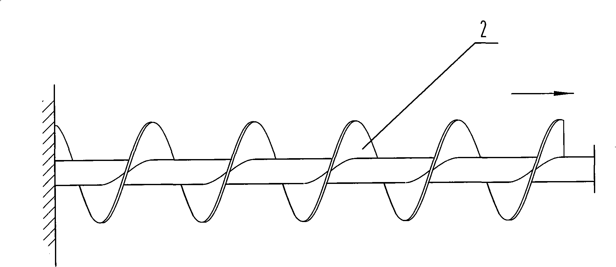
[0042] Such as Figure 1 ~ Figure 3 Shown, spiral blade winding molding method of the present invention is as follows:

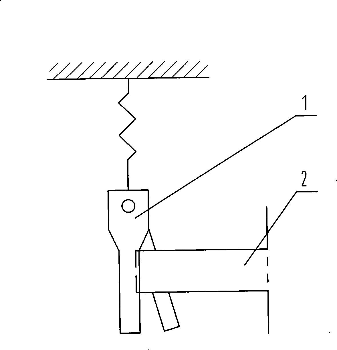
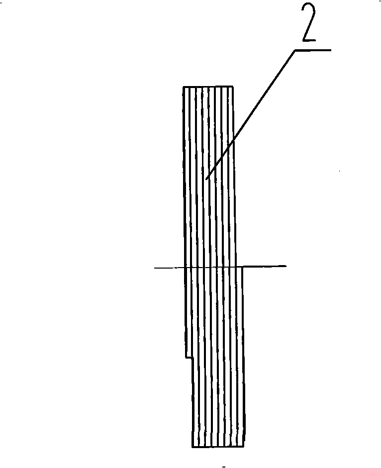
[0043] First pull out the end of the steel strip coil 2 from the horizontal coil rack (not drawn in the figure), and then pass through the discharge slot hole of the material guide frame 51 in a manner that the width of the steel strip is vertical, and then fix the steel strip 1 On the fixed mold 41, and make the inner surface of the steel band 1 close to the end face of the fixed mold 41, its lateral lower side vertically leans against the surface of the fixed mold center mandrel 412, and the movable and fixed molds are closed to clamp the steel strip.

[0044]The winding machine drives the transmission shaft 34 to rotate through the reducer 31, thereby driving the movable mold 42, the fixed mold 41, the passive mold 42, and the fixed mold 41 to pos...


PUM


Abstract

The present invention relates to a convolution forming method of a helical blade and a forming device thereof. A steel belt is fixed on a fixing mould; the fixing mould and a dynamic mould are closed to hold the steel belt; the transmission shaft of a convolution machine rotates to drive the steel belt to vertically rotate along with the central mandril of the fixing mould, so that the helical blade with the helical surface being overlapped is produced; the helical blade is stretched by a professional stretching device to obtain the required helical distance. The present invention also relates to a convolution forming device of a helical blade; an output shaft of a reducer of the device is connected with a transmission shaft through a transmission element; one side of the fixing mould is firmly connected with one end of the transmission shaft, and the other side of the fixing mould is provided with a central mandril; the two sides of the dynamic mould are supported on a guiding device; the rear side of the guiding device is connected with a press-molding device. A material guiding device is arranged at the outer side of the working surface of the fixing mould and the dynamic mould. The convolution forming method of the present invention reduces the production procedures, and improves the material utilization rate and the production efficiency; the thickness of the produced helical blade is equal, and the mechanics performance is uniform.

Description

technical field [0001] The invention relates to a forming method of a spiral blade, in particular to a vertical winding forming method of the spiral blade, and also relates to winding forming equipment of the spiral blade, which belongs to the technical field of pressure processing. Background technique [0002] Spiral blades are widely used as accessories of material conveying machinery. At present, the forming methods of spiral blades mainly include the following types: [0003] (1) Tailored welding combined tension forming [0004] First cut the steel plate into flange blanks, then tailor-weld the blanks piece by piece to form a barrel-shaped merged helix, and then weld one end of the merged helix on the transmission shaft to position, and the other end is pulled by a high-power pulling device. Stretch into spiral blade segments, and finally weld each spiral body segment by segment to form the final spiral blade. This method has low production efficiency, labor and time...

Claims


Application Information

Patent Timeline
Patent Type & Authority Applications(China)
IPC IPC(8): B21D53/78B21D11/06B21D22/20B21D37/10B21D43/02
Inventor 李悦
Owner ZHENJIANG BANGHE SPIRAL MFG
Why Eureka
Try Eureka