Cashmere card
A carding machine and cashmere technology, which is applied in the field of cashmere carding machines, can solve the problems of not being able to choose a suitable cashmere carding machine, waste of equipment resources, and large space occupation, and achieve low manufacturing and maintenance costs, prevent wool plugging, The effect of taking up little space
- Summary
- Abstract
- Description
- Claims
- Application Information
AI Technical Summary
Problems solved by technology
Method used
Image
Examples
Embodiment 1
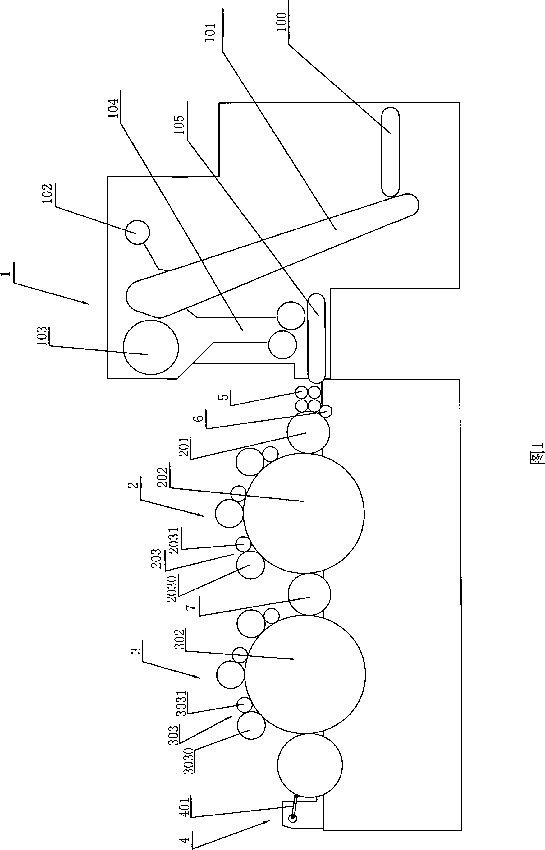
[0019] Referring to Fig. 1, a cashmere carding machine is provided with a feeding mechanism 1, an opening mechanism 2, a carding mechanism 3 and a stripping mechanism 4. The following is a detailed description of each of the above-mentioned institutions:
[0020] The feeding mechanism 1 is provided with a flat curtain 100, an oblique curtain 101, an even rake 102, a stripping roller 103 and a volume box 104. The wool raw material fibers are carried by the flat curtain 100 to the inclined curtain 101, and then picked up by the inclined curtain 101 and carried up to the rake 102, and the rake 102 knocks down the excess fiber raw materials for wool equalization, and it is left in place. After being carried to the top, the fiber raw material is stripped off by the front stripping roller 103 and falls into the volume box 104, and then evenly transported to the opening mechanism 2 through the pressure roller and the bottom flat curtain at the bottom of the volume box.
[0021] The ...
Embodiment 2
[0024] Except for the following records, refer to Example 1 for other relevant technical contents.
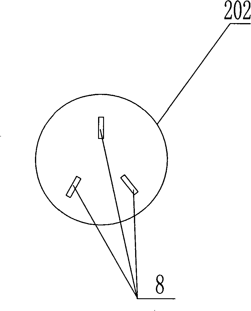
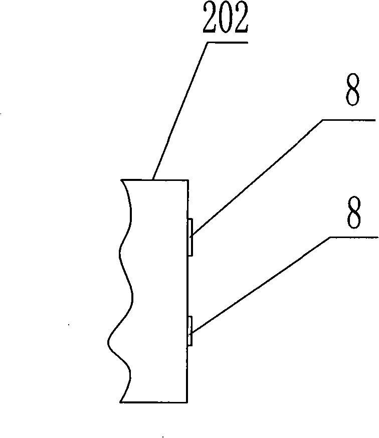
[0025] combine figure 2 and image 3 , taking the cylinder 202 as an example, an airflow generating part is respectively arranged on its two ends, the airflow generating part is a fan blade structure, and there are three sheet-shaped bodies 8, and the three sheet-shaped bodies 8 are radially fixed on the On the corresponding end face of the cylinder, the cylinder carries the flakes and rotates together to generate corresponding airflow during the rotation process.
Embodiment 3
[0027] Except for the following descriptions, refer to Embodiment 1 or Embodiment 2 for other relevant technical contents.
[0028] see Figure 4 , The stripping mechanism 4 includes a stripping roller 401 located in the rear position and a pair of upper and lower rolls 402, 403 located in the front position. The roll diameter of lower roll 403 is greater than the roll diameter of upper roll 402, and the roll diameter of following roll 403 can be identical with the roll diameter of stripping roll 401, also can take slightly larger than or slightly less than the mode of stripping roll 401 roll diameter certainly. The position of the lower roll 403 moves backward relative to the position of the upper roll 402, and the position of the lower roll 403 approaches the stripping roll 401 from the front and bottom.
PUM
 Abstract
Description
Claims
Application Information
 - R&D
- Intellectual Property
- Life Sciences
- Materials
- Tech Scout
- Unparalleled Data Quality
- Higher Quality Content
- 60% Fewer Hallucinations
Browse by: Latest US Patents, China's latest patents, Technical Efficacy Thesaurus, Application Domain, Technology Topic, Popular Technical Reports.
© 2025 PatSnap. All rights reserved.Legal|Privacy policy|Modern Slavery Act Transparency Statement|Sitemap|About US| Contact US: help@patsnap.com


