Drilling fluid cleaning system device

A purification system and drilling fluid technology, which is applied in earthwork drilling, wellbore flushing, wellbore/well parts, etc., can solve problems such as unreasonable structure layout, poor mixing uniformity, serious sedimentation, etc., and achieve favorable mud mixing efficiency, The effect of large stirring force and short mixing time

Inactive Publication Date: 2009-01-14
孙泽义
View PDF0 Cites 9 Cited by
  • Summary
  • Abstract
  • Description
  • Claims
  • Application Information

AI Technical Summary

Problems solved by technology

[0007] The purpose of the present invention is to improve the existing drilling fluid purification system device, by studying and solving the mud mixing mode and

Method used


Image

  • Drilling fluid cleaning system device
  • Drilling fluid cleaning system device
  • Drilling fluid cleaning system device

Examples


Embodiment Construction

[0021] The present invention will be further described below in conjunction with accompanying drawing.

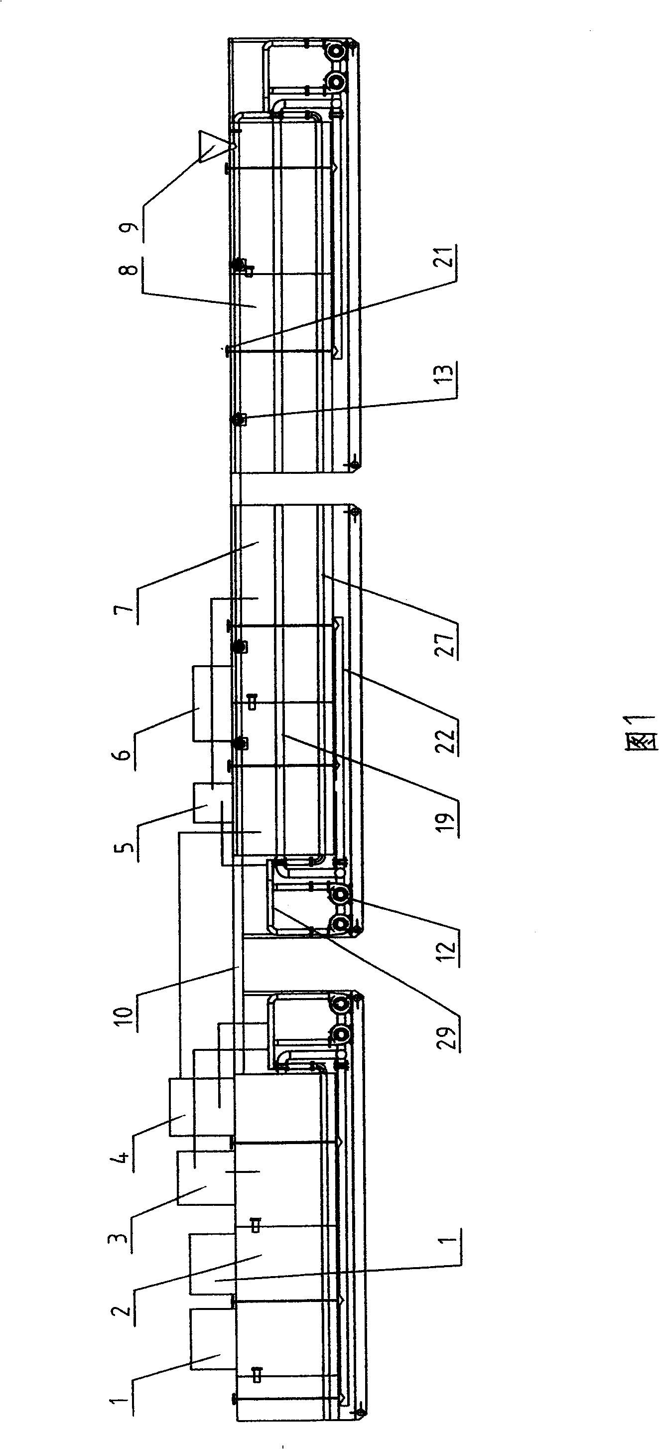
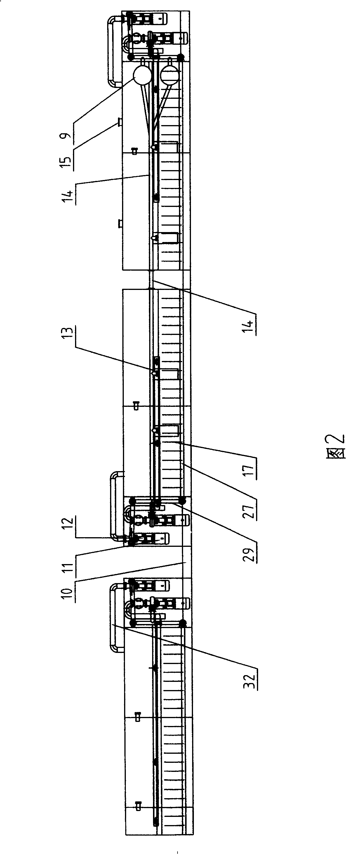
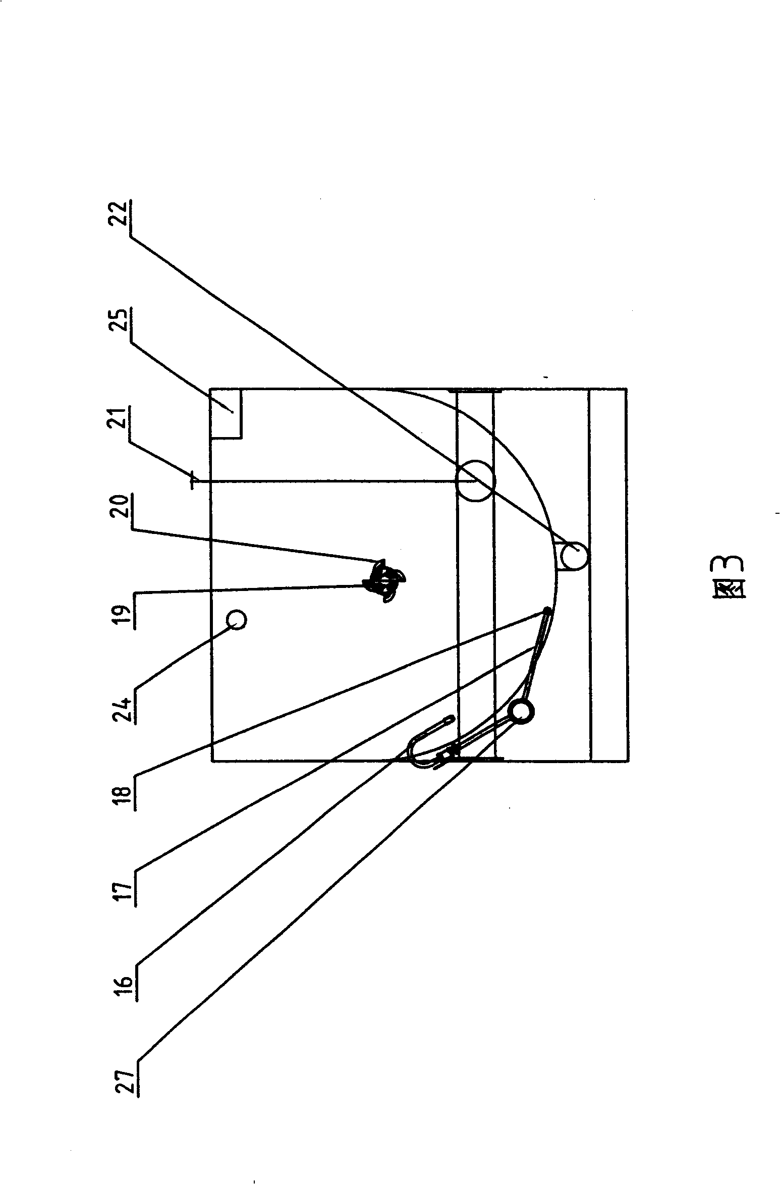
[0022] Referring to Fig. 1, Fig. 2 and Fig. 3, the drilling fluid purification system device includes a primary treatment tank 2 with a vibrating screen 1, a degasser 3 and a desander 4 on the top, a desilter 5, a centrifuge The post-treatment tank 7 of 6 is provided with the mud mixing tank 8 of the mixing funnel 9. According to the size of the drilling rig and the required drilling fluid reserve, a reserve tank can also be added between the post-processing tank and the mud mixing tank, and the mud can be filled between the tanks. Groove 10 communicates. In the system, each drilling fluid tank is provided with intercommunicating compartments, and each tank is provided with a central suction pipe 19 in the inner cavity that runs through each compartment of the tank, and a spraying main pipe 27 along each compartment of the tank is provided outside the tank. Two rows of inj...


PUM


Abstract

The invention discloses a drilling fluid purifying system and a device thereof, which are used for the circulating purification and ground configuration of the drilling fluid in the drilling operations of petroleum, geological exploration and non-excavation and the like. The drilling fluid purifying system and the device comprise an initial processing tank and a post processing tank which are provided with vibrating screens, deaeration devices, desanders, desilters and centrifugal machines as well as a slurry mixing tank provided with a mixing funnel, a central suction pipe penetrating through each bin of the tank is respectively arranged in the inner cavity of each tank, a main spraying pipe communicated with each bin of the tanks is arranged outside the tanks, a bottom suction pipe communicated with each bin of the tanks is arranged below the tanks, slurry dividing pipes connected to the mixing funnel are arranged at the top of the slurry mixing tank and the adjacent tank, a drilling fluid output pipe is arranged at the rear end of the system, the central suction pipe and the bottom suction pipe of each tank are connected into the suction end of a sand pump of each tank, the main spraying pipe of each tank and the related equipment on the tank top are connected into the paralleled discharging pipes of the sand pump, and the sand pump of each tank or each tank is respectively connected with the discharging ends of other sand pumps in parallel through the main spraying pipes. The invention aims to solve the defects of bad mixing uniformity, low efficiency and much sediment in the existing purifying device by utilizing a reasonable structure.

Description

technical field [0001] The invention relates to the circulation and purification of drilling fluid for drilling operations such as petroleum, geological exploration, and non-excavation, and can also be used for ground preparation of the drilling fluid for these operations. Background technique [0002] At present, the drilling fluid purification system devices used in the above fields at home and abroad generally consist of a primary treatment tank and a post-treatment tank with a vibrating screen, a degasser, a desander, a desilter, and a centrifugal separator installed on the top, and a mixing funnel is installed. The mud mixing tank and the storage tank to be added according to the needs are arranged according to the process route. There are mud tanks and pipelines connecting each tank. The tank body is a horizontal cuboid tank with a compartment. Equipped with blade stirrer. When the system is working, the drilling fluid from the well is dragged by the sand pump and pur...

Claims


Application Information

Patent Timeline
IPC IPC(8): E21B21/06
Inventor 孙泽义
Owner 孙泽义
Why Eureka
Try Eureka