Polarization conversion unit, polarization conversion device, and projector

A technology of a conversion unit and a conversion device, applied in the field of projectors, can solve the problems of poor optics, increased manufacturing costs, and damage to optical properties.

Inactive Publication Date: 2011-07-06
SEIKO EPSON CORP
View PDF1 Cites 0 Cited by
  • Summary
  • Abstract
  • Description
  • Claims
  • Application Information

AI Technical Summary

Problems solved by technology

[0005] However, as described in Patent Document 1, in the case of using an ultraviolet curing adhesive to bond the phase difference plate to the light beam exit side of the transparent member, since the surfaces of the transparent member and the phase difference plate are not perfectly flat, it is difficult to Make the surface of the beam incident side of the phase difference plate, and the surface of the light beam exit side of the transparent member (translucent member), stick together, and the surface of the beam incident side of the phase difference plate, and the transparent member (translucent member) There is a small gap below the wavelength of light between the surfaces on the beam exit side
Therefore, there is a problem that it is easy to cause optical defects (interference fringes, etc.) in the projected image to damage the optical characteristics.
And, can enumerate such problem: in the manufacturing process that retardation plate is bonded to the light beam exit side of transparent member, when the retardation plate that is coated with ultraviolet curable adhesive is placed on the light beam of transparent member, In the case of the surface on the emission side, if the position where the phase difference plate is placed is not appropriate for some reason, it is impossible to keep the phase difference plate in place without reinstalling it, which is the main reason for the increase in manufacturing cost. reason
In short, these have become the main reasons for the increase in manufacturing costs

Method used


Image

  • Polarization conversion unit, polarization conversion device, and projector
  • Polarization conversion unit, polarization conversion device, and projector
  • Polarization conversion unit, polarization conversion device, and projector

Examples


Embodiment approach

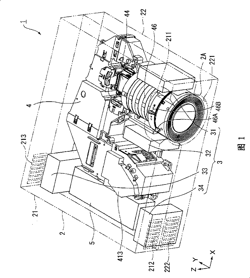
[0033] figure 1 It is a perspective view explaining the schematic structure of the projector in embodiment. refer to figure 1 , the configuration of the projector 1 will be described.

[0034] The projector 1 is composed of an exterior casing 2 having a substantially rectangular parallelepiped shape as a whole, and a cooling unit 3 for cooling heat accumulated in the projector 1 . Further, the projector 1 includes an optical unit 4 that optically processes light beams emitted from a light source to form an optical image based on image information, and a configuration that supplies power supplied from outside through a power cable (not shown) to the projector 1. The power supply unit 5 of the component is constituted.

[0035] The exterior casing 2 is formed of various metal materials, including: an upper casing 21 constituting the top, front, side, and back of the projector 1 respectively, and an upper casing 21 constituting the bottom, front, side, and The lower casing 22 o...


PUM


Abstract

The present invention discloses a polarization conversion unit, a polarization conversion apparatus and a projector. A polarization conversion unit includes a polarization splitting element array including a plurality of polarization splitting films for splitting the incident light beam into two types of linearly-polarized light beams, a plurality of reflecting films for reflecting either one of the linearly-polarized light beams obtained by the polarization splitting films, and a translucent member provided with the polarization splitting films and the reflecting films, a plurality of retardation plates each formed of a quartz crystal member and for converting a polarization axis of either one of the linearly-polarized light beams obtained by the polarization splitting films into a polarization axis of the other of the linearly-polarized light beams, and a spacer member having a predetermined thickness and for bonding end sections of the retardation plates to a light beam exit side of the translucent member.

Description

technical field [0001] The present invention relates to a polarization conversion unit, a polarization conversion device provided with the polarization conversion unit, and a projector provided with the polarization conversion device. Background technique [0002] Conventionally, in projectors and the like, for the purpose of improving the utilization efficiency of the light beam emitted from the light source, a polarization conversion device that converts the emitted light beam into one type of linearly polarized light is used. Moreover, the polarization conversion device is composed of a polarization conversion unit, and the polarization conversion unit includes: a plurality of polarization separation films that are arranged obliquely with respect to the incident beam to separate the incident beam into two types of linearly polarized beams, and are alternately arranged in parallel Between each polarization separation film, a plurality of reflection films that reflect any o...

Claims


Application Information

Patent Timeline
Patent Type & Authority Patents(China)
IPC IPC(8): G02B27/28G03B21/00
CPCG03B33/12G03B21/14G02B27/285G03B21/16G03B21/2073
Inventor 酒井洋平
Owner SEIKO EPSON CORP
Why Eureka
Try Eureka