Method and apparatus for adjusting phase as well as light modulator

A phase adjustment and phase technology, applied in the field of communications, can solve the problems of phase difference, PD signal degradation, PD response signal and low-frequency disturbance signal asynchrony, etc., to reduce costs and improve reliability.

Inactive Publication Date: 2012-04-04
HUAWEI TECH CO LTD
View PDF0 Cites 0 Cited by
  • Summary
  • Abstract
  • Description
  • Claims
  • Application Information

AI Technical Summary

Problems solved by technology

In order to make the PD response signal obtained from the modulator obtain an amplitude signal that satisfies the calculation of Vpp even when the signal-to-noise ratio is very low, both methods use multi-stage filtering and multi-stage amplification circuits. Due to the multi-stage filtering and multi-stage amplification The phase of the circuit changes differently at different temperatures, which will cause asynchrony between the PD response signal and the low-frequency disturbance signal, and a phase difference will appear, which will cause a deviation in the calculation of Vpp and reduce the control accuracy of the Bias voltage; if part of the amplifier circuit is removed , filter circuit to reduce the phase difference, which will cause the degradation of the PD signal
Therefore, the problem of phase difference between the PD response signal and the low-frequency disturbance signal always plagues the control accuracy of the Bias voltage

Method used


Image

  • Method and apparatus for adjusting phase as well as light modulator
  • Method and apparatus for adjusting phase as well as light modulator
  • Method and apparatus for adjusting phase as well as light modulator

Examples


Embodiment Construction

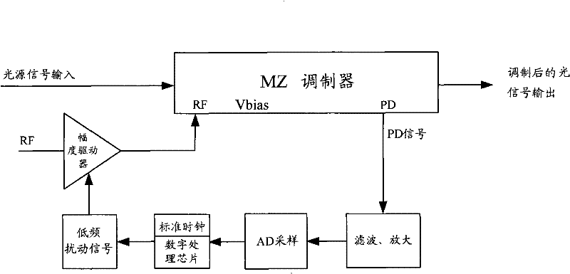
[0044] The specific implementation scheme for adjusting the phase difference between the response signal and the low-frequency disturbance signal will be described in detail below through the embodiments of the present invention. combine first image 3 and Figure 4For a detailed description of Embodiment 1 of the present invention, see image 3 , in this embodiment, the modulator is an MZ type modulator, which may be a lithium niobate modulator. In this modulator, the electrical signal is obtained after photoelectric conversion through the PD terminal, and AD sampling is performed after filtering and amplifying. The digital processing chip uses the sampled value to judge, and uses the judged result to adjust the low-frequency disturbance signal. For the specific implementation process, see Figure 4 , including the following steps:

[0045] Step 401: Obtain a response signal with a low-frequency disturbance signal, and obtain a response signal at the frequency of the low-...


PUM


Abstract

The present invention discloses a phase adjustment method, a device and an optical modulator thereof. The method comprises the following steps: acquiring response signals with low-frequency disturbance signals; adopting the response signals to acquire the response signals of the frequency of the low-frequency disturbance signals; dividing the standard clock cycle of the preset length into two equal time slots; using a sampling clock to sample the response signals in the time slots; acquiring the sampling value of the response signals in the two time slots; acquiring the representative value of all the sampling values in either time slot; acquiring the representative difference value between two representative values; acquiring the adjustment difference value between the representative difference value and the preset threshold; and moving the phase of the low-frequency disturbance signals for a corresponding angle in accordance with the adjustment difference value, so that the phase difference between the low-frequency disturbance signals and the response signals can maintain constant. The present invention also discloses a device and an optical modulator, which are used for phase adjustment.

Description

technical field [0001] The present invention relates to the technical field of communication, in particular to a phase adjustment method, device and optical modulator. Background technique [0002] With the deepening of optical and electronic communication research, optical communication has developed rapidly. In the optical transmission system, the transmission distance without electrical relay has reached hundreds of kilometers. During optical fiber transmission, an external modulator is used to make the laser work in continuous wave mode, which simply and completely overcomes the influence of frequency chirp. In addition, it can provide higher speed, higher extinction ratio and higher power. Therefore, external modulation technology is ideal for ultra-high-speed, long-distance optical transmission. [0003] Most of the current optical modulators are Mach-Zehnder modulators, among which lithium niobate (LiNbio3) modulators are the main ones. The working principle of th...

Claims


Application Information

Patent Timeline
Patent Type & Authority Patents(China)
IPC IPC(8): H04B10/155G02B26/06H04B10/50H04B10/58
CPCH04B10/505G02F1/0123H04B10/58
Inventor 樊晓燕
Owner HUAWEI TECH CO LTD
Why Eureka
Try Eureka