
Optical metrological scale and laser-based manufacturing method therefor

An optical metrology and laser technology, applied in manufacturing tools, laser welding equipment, measuring devices, etc., which can solve problems such as unmentioned temperature problems and undisclosed problems

Inactive Publication Date: 2009-01-28
THE GSI GRP LLC
View PDF8 Cites 16 Cited by
  • Summary
  • Abstract
  • Description
  • Claims
  • Application Information

AI Technical Summary

Problems solved by technology

The '5586 patent states that the '131 patent does not disclose a method of performing this operation, nor does it mention how to overcome the temperature problem

Method used


Image

  • Optical metrological scale and laser-based manufacturing method therefor
  • Optical metrological scale and laser-based manufacturing method therefor
  • Optical metrological scale and laser-based manufacturing method therefor

Examples


Embodiment Construction

[0080] Terms used in the following descriptions are provided with brief descriptions and are intended to be explanatory rather than limiting. In the context of "chaotic" structures referred to in this specification, "chaos" generally refers to an observable structure characterized by the formation of a disorganized or chaotic mixture of matter at the location of laser impingement. By way of example, the chaotic structure may be a collection of molten matter with irregular shapes and varying reflectivities. To illustrate, "non-chaotic" or "well-structured" could be a region with a smooth measurable spatial profile, or a quasi-periodic spatial profile with regular regions of uniform color in a given direction. A "trench" or "trough-like" structure has a relatively long and narrow shallow concave shape, sometimes U-shaped or V-shaped in cross-section, relative to the surrounding plane. "Energy density" and "fluence" are a group of synonyms, which refer to the energy per unit are...


PUM


Abstract

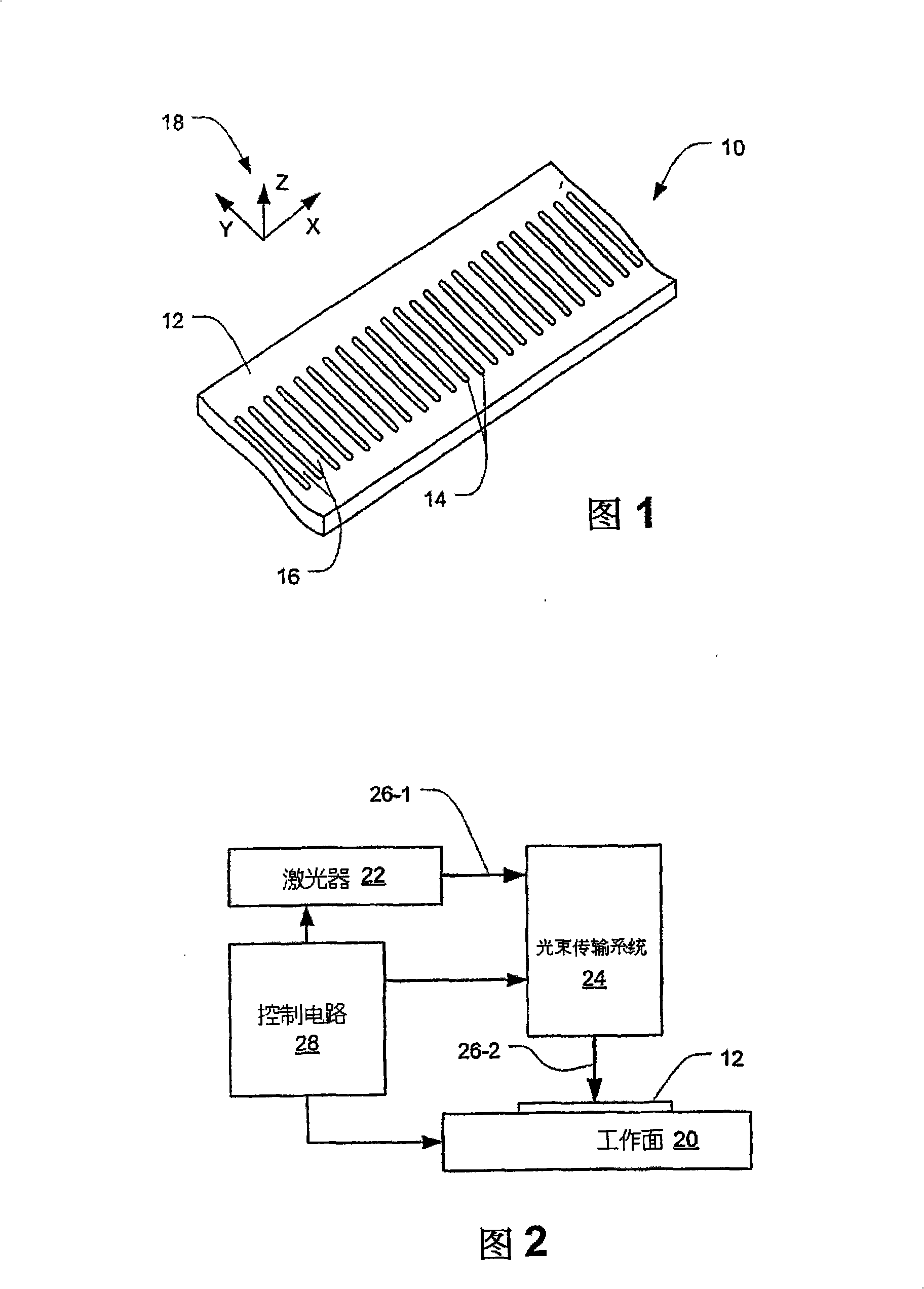
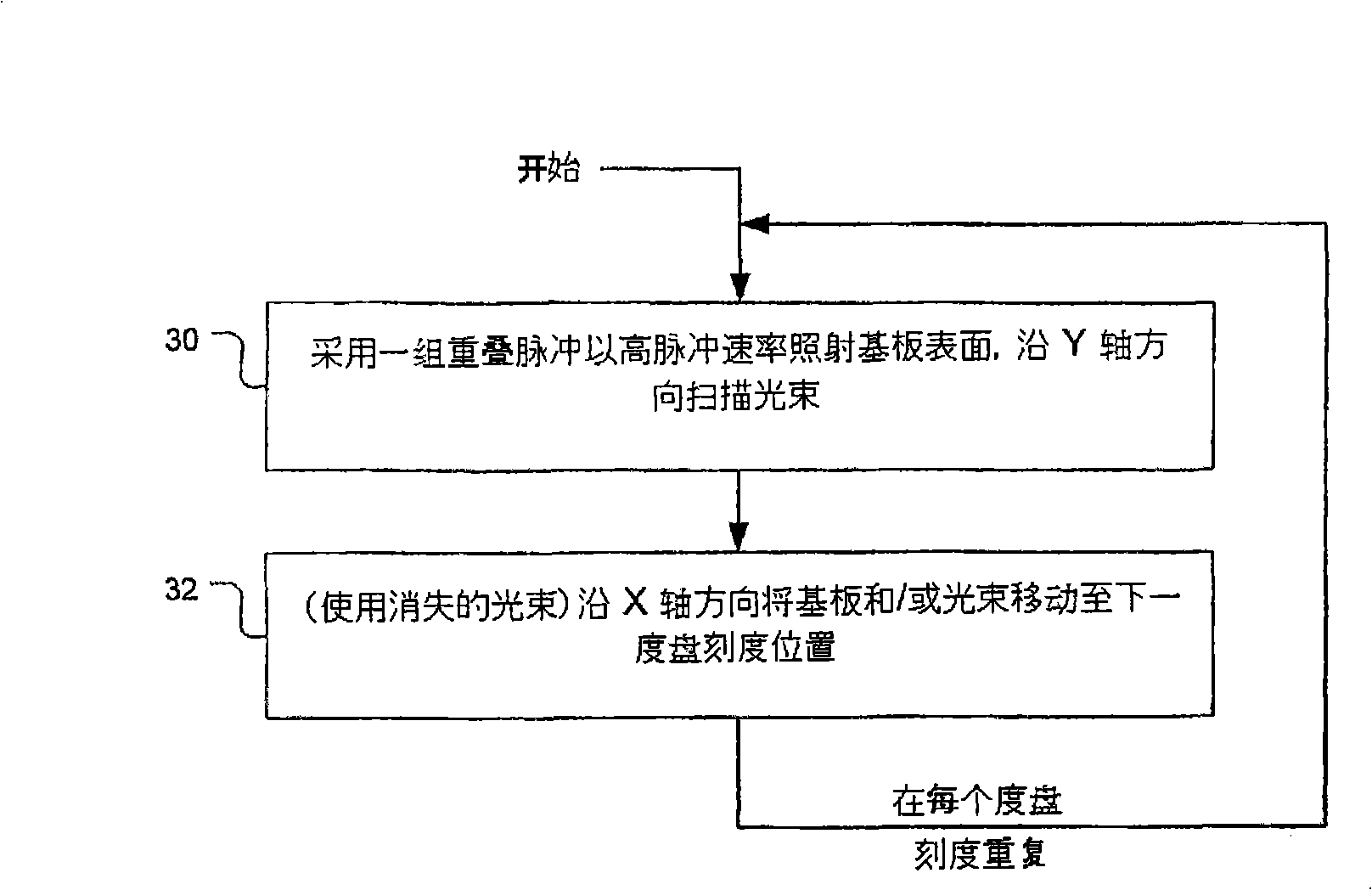
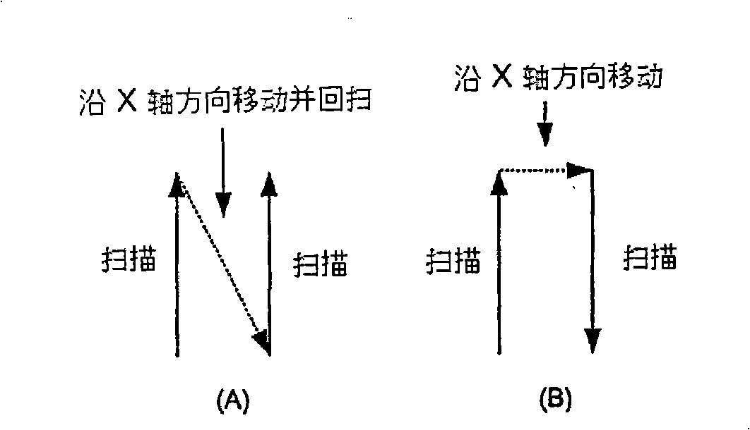
A reflective metrological scale has a scale pattern of elongated side-by-side marks surrounded by reflective surface areas of a substrate, which may be a nickel-based metal alloy such as Invar TM or Inconel TM and may be a thin and elongated flexible tape. Each mark has a furrowed cross section and may have a depth in the range of 0.5 to 2 microns. The central region of each mark may be rippled or ridged and may be darkened to provide an enhanced optical reflection ratio with respect to surrounding reflective surface areas. A manufacturing method includes the repeated steps of (1) creating a scale mark by irradiating a surface of the substrate at a mark location with a series of overlapped pulses from a laser, each pulse having an energy density of less than about 1 joule per cm<2>, and (2) changing the relative position of the laser and the substrate by a displacement amount defining a next mark location on the substrate at which a next mark of the scale is to be created.

Description

technical field [0001] This invention relates to the formation of readable precision structures, patterns, graduations or other markings on gauges and similar instruments by irradiation with energy beams. The invention particularly relates to, but is not limited to, forming a graduated pattern on an object, such as a graduated structure on a dial (eg, in an optical encoder) for metrological purposes. Background technique [0002] Some of the main problems encountered when using energy beams to mark the surface or subsurface of a material are as follows: dimensional control of the energy beam relative to the surface / subsurface (e.g. maintaining the exact size of the graduation marks); obtaining accurate occupancy void ratio (i.e. the ratio of the marked surface to the unmarked surface); obtaining a consistent structure (i.e. neat and smooth structure edges and a consistent structure surface); correct choice of energy beam parameters such as energy density (per unit area ener...

Claims


Application Information

Patent Timeline
Patent Type & Authority Applications(China)
IPC IPC(8): C23F1/08C23F4/02C23F17/00
CPCB23K26/367B41M5/24G01D5/34707B23K26/364C23F1/08C23F4/02C23F17/00B23K26/36B23K26/0622B23K26/352C22C19/05B23K2103/08
Inventor 科特·普尔休斯图亚特·A·道德森Ⅱ布拉德利·L·亨特唐纳德·V·斯马特皮埃尔-伊夫·马布乔纳森·S·埃尔曼
Owner THE GSI GRP LLC
Learn More