
Imaging method and device based on orthogonal multiple frequency ultrasonic stable-state echo signal

A technology of echo signal and multi-frequency ultrasound, which is applied in the directions of sound wave re-radiation, ultrasound/sonic wave/infrasonic wave diagnosis, measuring device, etc., which can solve the difficult problem of estimating reflected echo, longitudinal resolution and sensitivity contradiction, difficult Estimate multiple interface reflection echoes and other issues to achieve the effects of easy detection, improved longitudinal resolution, and reduced requirements

Inactive Publication Date: 2009-02-04
SOUTH CHINA UNIV OF TECH
View PDF0 Cites 18 Cited by
  • Summary
  • Abstract
  • Description
  • Claims
  • Application Information

AI Technical Summary

Problems solved by technology

For the case of multiple reflection interfaces, the result is the superposition of multiple reflection echoes. At this time, it is difficult to estimate the reflection echo of each interface.
[0005] It can be seen that the method based on pulse imaging will bring a contradiction between longitudinal resolution and sensitivity, and the method of obtaining ultrasonic imaging with single-frequency continuous wave is difficult to estimate the reflected echoes of multiple interfaces

Method used


Image

  • Imaging method and device based on orthogonal multiple frequency ultrasonic stable-state echo signal
  • Imaging method and device based on orthogonal multiple frequency ultrasonic stable-state echo signal
  • Imaging method and device based on orthogonal multiple frequency ultrasonic stable-state echo signal

Examples


Embodiment Construction

[0035] The specific embodiments of the present invention will be further described below in conjunction with the accompanying drawings.

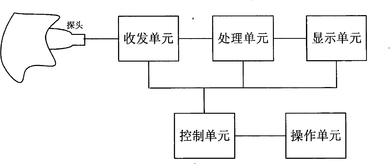
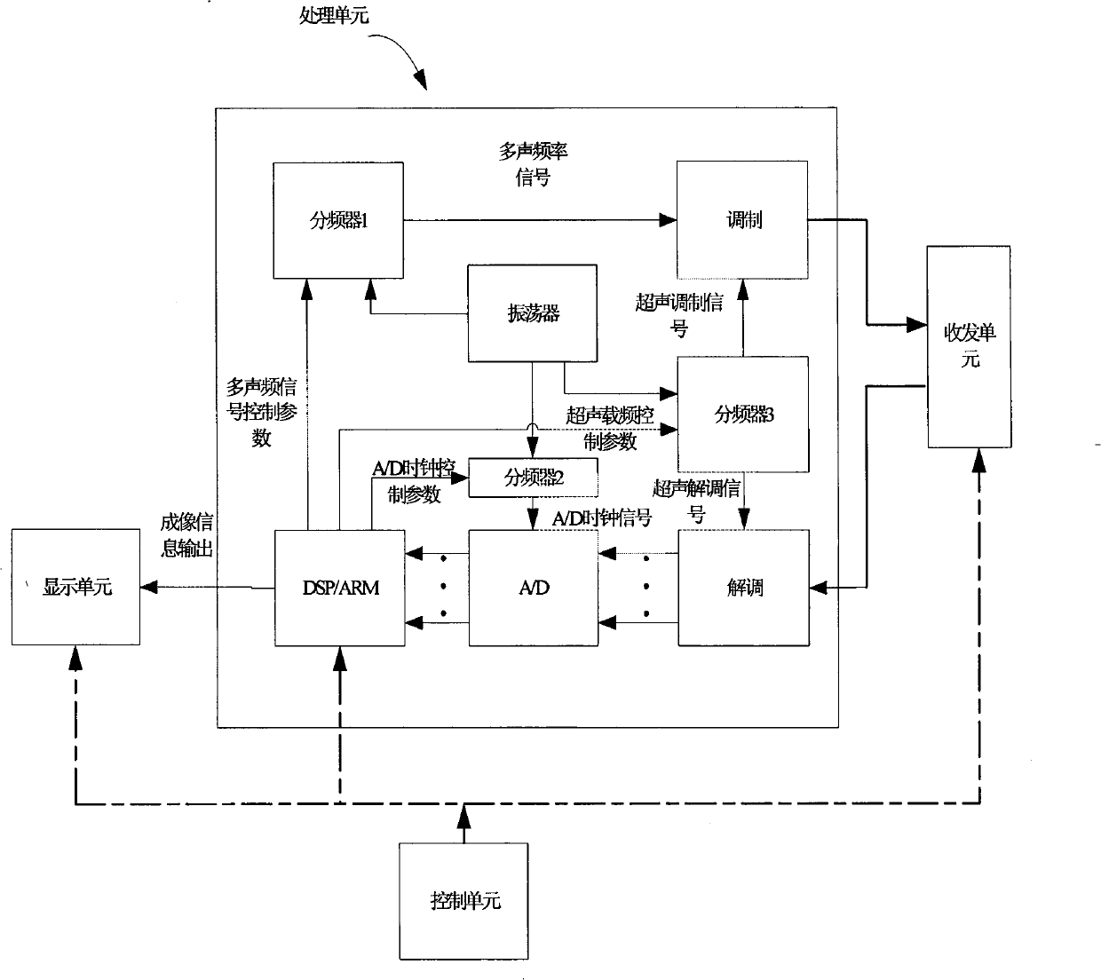
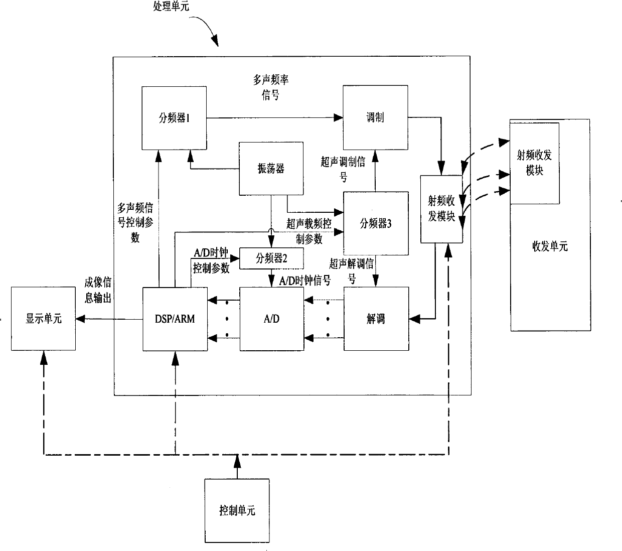
[0036] Such as figure 1 As shown, the device of the present invention includes an ultrasonic probe, an operation unit, a control unit, a transceiver unit, a processing unit and a display unit. Such as figure 2 As shown, the processing unit includes a digital signal processor (DSP or single-chip processor ARM, etc.), a modem, an oscillator, several frequency dividers and an analog-to-digital converter (A / D). The oscillator uses a 20M crystal oscillator, the frequency divider is implemented with a phase-locked loop circuit, the modulator and demodulator are implemented with a multiplication circuit, and the analog-to-digital converter and digital signal processor are implemented with a TI DSP chip TMS 320C2812.

[0037] The ultrasonic probe is an ultrasonic transducer, which is composed of a piezoelectric material, that is, piezoelectric ce...


PUM


Abstract

The invention discloses an imaging method and a device on the basis of orthogonal multi-frequency ultrasonic steady echo signal. The method uses an orthogonal frequency division multiplexing modulation type to form multi-frequency continuous baseband signals which are orthogonal with each other; the multi-frequency continuous baseband signals are modulated as multi-frequency ultrasonic continuous emission signals and sent out by an ultrasonic probe; the ultrasonic probe detects the steady echo signals which are reflected back; the steady echo signals are equivalent to the superposing signals; the received multi-frequency continuous baseband signals after modulation are orthogonally decomposed, each path of receiving signals are decomposed by the characteristic that each path of signals are orthogonal with each other, the amplitude of each interface reflection echo and the position thereof corresponding to the incident interface are calculated so as to carry out the image forming. The device of the invention comprises an ultrasonic probe, a control unit, and an operation unit, a receiving / emitting unit, a processing unit and a display unit which are respectively connected with the control unit; the ultrasonic probe is connected with the receiving / emitting unit; the processing unit is respectively connected with the receiving / emitting unit and the display unit; the method and the device of the invention has precise image forming and good anti-interference performance, and reduces the cost by adopting a single probe.

Description

technical field [0001] The present invention relates to ultrasonic imaging technology, in particular to a method for constructing mutually orthogonal continuous multi-frequency ultrasonic signals by means of an orthogonal frequency division multiplexing (OFDM) modulation method, and measuring the steady-state echo signals of the multi-frequency ultrasonic signals for imaging with the device. Background technique [0002] At present, there are two general ultrasonic echo imaging methods: based on single pulse and based on single frequency continuous wave. The imaging method based on single pulse is realized by utilizing the physical characteristics that the ultrasonic wave will reflect when it encounters the inhomogeneous interface of the medium on the propagation path. The sending end sends a pulse to the human tissue. Due to the different acoustic impedances of human tissue and organs, the ultrasonic wave reflects echoes on the uneven interface, detects these echo signals,...

Claims


Application Information

Patent Timeline
IPC IPC(8): A61B8/00G01S15/89G01S15/02
Inventor 韦岗曹燕宁更新
Owner SOUTH CHINA UNIV OF TECH
Learn More