Lathe-milling consubstantial machine tool

A machine tool, turning and milling technology, applied in metal processing mechanical parts, metal processing equipment, manufacturing tools, etc., can solve the problems of large structure size, large work space, inconvenient movement, etc., and achieve easy lightweight, wide applicability, Easy-to-use effects

Inactive Publication Date: 2009-02-04
SHENZHEN UNIV +1
View PDF0 Cites 13 Cited by
  • Summary
  • Abstract
  • Description
  • Claims
  • Application Information

AI Technical Summary

Problems solved by technology

2) The current machine tool is mainly designed for processing metal materials. Due to the requirements of rigidity and strength, the material used in the machine tool is basically steel, and the structure size is large, the volume is heavy, and the required work site is large. They are used for teaching purposes that only need to process soft non-metallic materials to achieve the purpose, so they appear to have greater mechanical redundancy, and have the disadvantages of being inconvenient to move and carry.

Method used


Image

  • Lathe-milling consubstantial machine tool
  • Lathe-milling consubstantial machine tool
  • Lathe-milling consubstantial machine tool

Examples


Embodiment approach 2

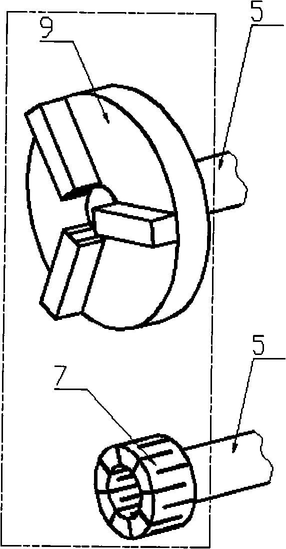
[0036] Embodiment 2 differs from Embodiment 1 in that this embodiment describes another specific spindle device structure. refer to Figure 7 , said main shaft device 4 is a kind of split main shaft. The main shaft device 4 includes a box body 4-1, a main shaft motor 4-2, a main shaft motor bracket 4-3, a pulley 4-4, a belt 4-5, a pulley 4-6 and a main shaft 5. The main shaft motor support 4-3 is arranged on the box body 4-1, and the main shaft motor 4-2 is installed on the main shaft motor support 4-3. The main shaft 5 traverses the casing 4-1, and the rotation centerline of the output shaft of the main shaft motor 4-2 is arranged parallel to the rotation centerline of the main shaft 5. The belt pulley 4-6 that is arranged on the main shaft 5 is connected with the belt pulley 4-4 that is arranged on the output shaft of the main shaft motor 4-2 through the belt 4-5, and the rotary motion of the main shaft 5 around its own rotation center line is passed by the rotation of the...

Embodiment approach 3

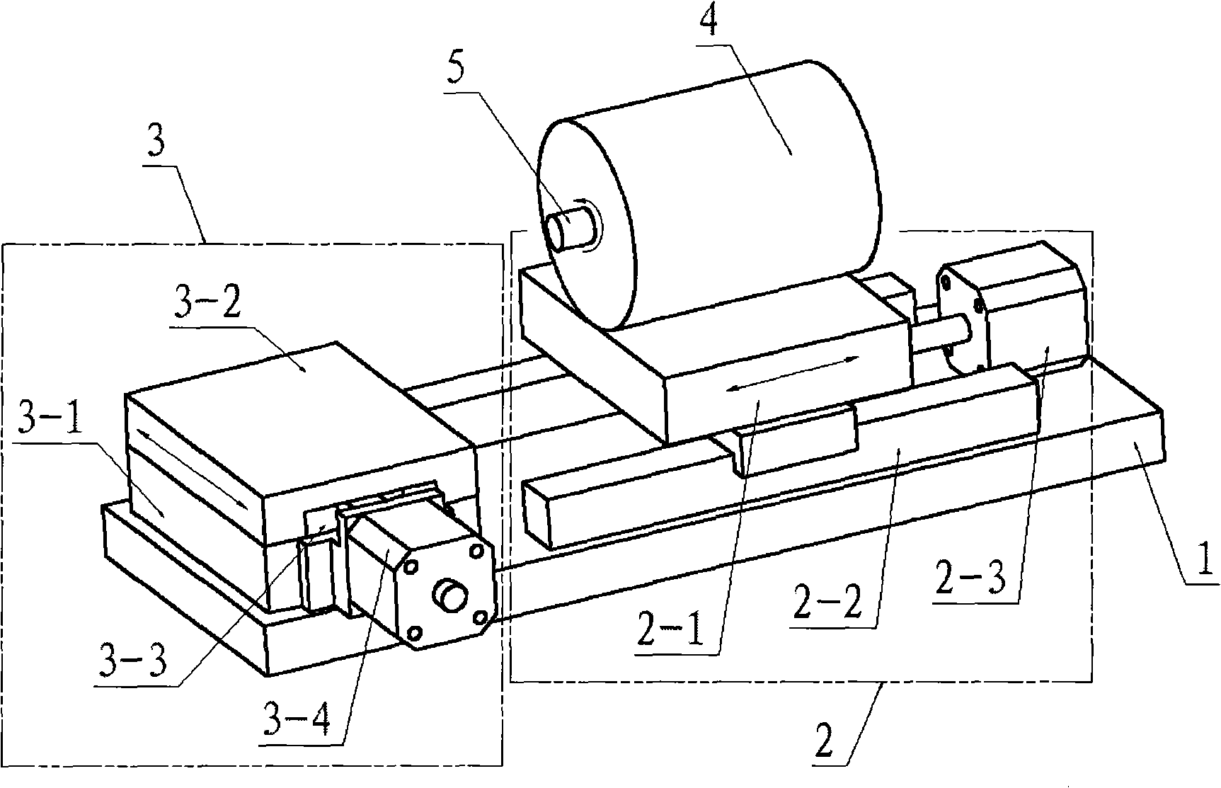
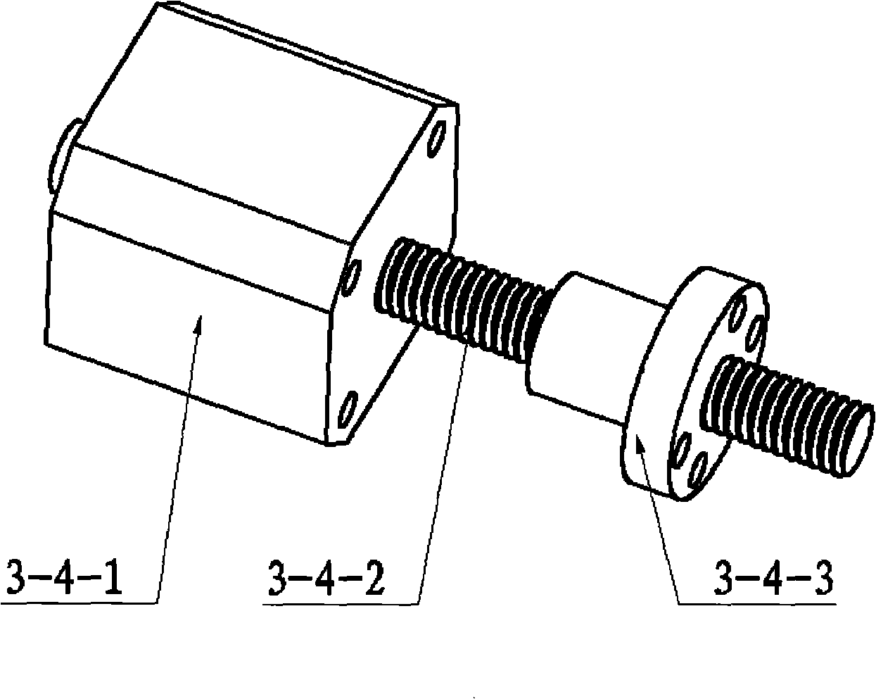
[0037] The difference between embodiment 3 and embodiment 1 or 2 is that this embodiment describes another improved structure of the work slide and the rotary table. like Figure 8 , The first working slide table 2 includes a slider 2-1, a rolling guide rail 2-2, a motor 2-3, and a hand wheel 2-4. The handwheel 2-4 is arranged on the motor 2-3 shaft, and the rotation of the handwheel 2-4 drives the linear reciprocating motion of the slider 2-1. like Figure 9 , The second working slide table 3 includes a slide table base 3-1, a slide block 3-2, a rolling guide rail 3-3, an integrated motor-screw nut pair 3-4 and a hand wheel 3-5. The handwheel 3-5 is arranged on the motor 3-4-1 shaft, and the rotation of the handwheel 3-5 drives the linear reciprocating motion of the slider 3-2. like Figure 10 , the third working slide 6 includes a slide base 6-1, a slider 6-2, a rolling guide 6-3, an integrated motor-screw nut pair 6-4 and a hand wheel 6-5. The hand wheel 6-5 is arrange...


PUM


Abstract

The invention provides a machine tool with the functions of cutting and milling simultaneously, which comprises a base, a work slipway and a spindle device; wherein, the work slipway comprises a first work slipway and a second work slipway; the first work slipway adopts a rolling guide for support and adopts a motor-lead-screw-nut as auxiliary driver; the second work slipway adopts a rolling guide for support and adopts a one-piece motor-lead-screw-nut as auxiliary driver; the spindle device is arranged on the first work slipway in a horizontal way; the movement directions of the two work slipways are orthogonally arranged. When the machine tool is used as a milling machine, the machine tool also comprises a third work slipway and a milling chuck; when the machine tool is used as a cutting machine, the machine tool also comprises a chuck and a cutting off tool rest; when the machine tool is used as another milling machine, the machine tool also comprises a rotary work table and a milling chuck.

Description

technical field [0001] The invention relates to a machine tool, in particular to a machine tool capable of realizing turning and milling in one body. Background technique [0002] Existing machine tool, function is all comparatively single. Among them, the lathe generally rotates the workpiece clamped on the chuck, and the tool performs cutting feed movement, and basically uses the spindle device to fix and the worktable to move to achieve processing. Among the milling machines, the spindle device of the vertical milling machine is arranged vertically. The spindle device does not move up and down during processing, and the vertical feed is realized by the up and down movement of the worktable. The spindle device of the horizontal milling machine is arranged horizontally, the center line of the spindle rotation is parallel to the two worktable surfaces, and the vertical feed is also realized by moving the worktable up and down. The worktables of vertical and horizontal mill...

Claims


Application Information

Patent Timeline
Patent Type & Authority Applications(China)
IPC IPC(8): B23P23/02B23Q1/26B23B19/02
Inventor 王华权刘茁
Owner SHENZHEN UNIV
Why Eureka
Try Eureka