Bent tube type slag water sealing squeezing slag removal machine

A technology of bent pipe and slag discharger, which is applied in the petroleum industry and the manufacture of combustible gas, etc., can solve the problems of reducing the output of gas-making furnaces, poor working environment, and waste of energy, so as to improve the reliability of safe production and improve the efficiency Working hours, the effect of solving gas leakage

Inactive Publication Date: 2011-06-15
湖北三盟机械制造有限公司
View PDF0 Cites 0 Cited by
  • Summary
  • Abstract
  • Description
  • Claims
  • Application Information

AI Technical Summary

Problems solved by technology

[0003] 1. Due to the open slag discharge method, the working pressure in the furnace is zero during slag discharge, forcing the gas generator to stop production during slag discharge, and can only work in a periodic intermittent production mode, which reduces the gas production to a certain extent furnace output
[0004] 2. Since the slag storage tank must be sprayed with water to cool before slag discharge, the wet slag will adhere to the sealing surface of the slag discharge port when it flows out, seriously affecting its sealing effect, causing a large amount of sewage and a small amount of gas to leak out, both pollute the environment and waste energy
[0005] 3. Due to the limitation of its intermittent slag discharge method, it can only be transported multiple times with a trolley, the working environment is harsh, and the labor intensity of the workers is relatively high, so it is difficult to realize fully automatic mechanized production

Method used


Image

  • Bent tube type slag water sealing squeezing slag removal machine
  • Bent tube type slag water sealing squeezing slag removal machine

Examples


Embodiment Construction

[0020] Specific embodiments of the present invention will be described in detail below in conjunction with the accompanying drawings.

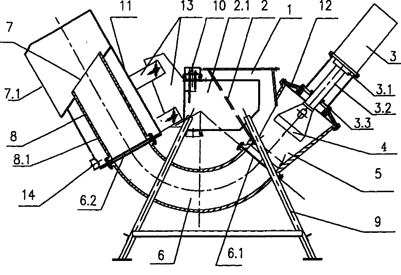
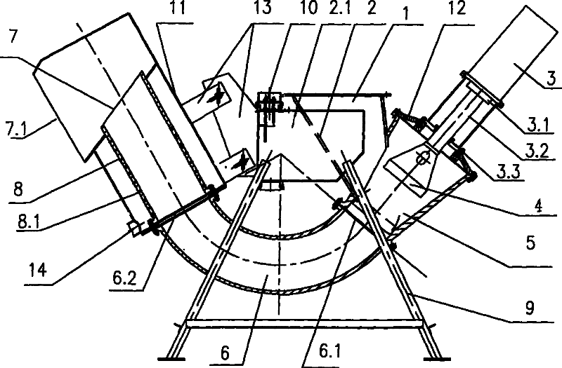
[0021] The present invention includes a casing, a pressure head and its driving part. The pressure head 4 driven by the driving part is placed in the compression chamber 5; It is connected with the curved casing 6 through a natural transition, and the bend of the curved casing 6 is lower than the compression chamber 5; the other end of the curved casing 6 is the slag outlet 7.

[0022] A water inlet 2 is arranged on the side of the slag feeding funnel. The water inlet 2 is communicated with the replenishing water tank 2.1, so that the water level in the slag-feeding funnel is equal to the water level of the replenishing water tank. A water level controller 10 is arranged in the replenishing water tank, and the control water level is higher than the sealing port 3.3 on the compression chamber 5, so as to ensure that the sealing port 3.3 obtain...


PUM


Abstract

The present invention provides a bent-tube type slag water sealing and squeezing slag extractor. A driving part pushes a squeeze head into a squeeze chamber; the outlet of a slag-feeding funnel is connected with the squeeze chamber which is connected with one end of a bent shell; the other end of the bent shell is a slag outlet; the bent part of the bent shell is lower than a compression chamber;and the side of the slag-feeding funnel is communicated with a water-replenishing tank. The compression chamber is inclined downwards; the lower opening of the compression chamber is connected with the bent shell in the form of natural transition; a water level controller is arranged inside the water-replenishing tank; and the water level of the water-replenishing tank is higher than the sealed opening of the upper opening of the compression chamber. A slag water separation section, which is assembled between the bent shell and the slag outlet, comprises a material-discharging shell connectedwith the bent shell; wherein, water-filtering holes are arranged on the tubular wall of the material-discharging shell; the slag outlet is the outlet of the material-discharging shell; a shield larger than the material-discharging shell is nested outside the material-discharging shell; both ends of the shield are hermetically connected with the material-discharging shell; and the lower part of the shield is provided with a water outlet. The driving part adopts a hydraulic cylinder.

Description

technical field [0001] The invention relates to an elbow type slag-water sealing extrusion slag discharger, which is mainly used as supporting equipment for discharging coal slag from the bottom of a fixed-layer gas generator (commonly known as a gas generator in the industry). Especially the automatic continuous extrusion slagging machine for gas generator. Background technique [0002] At present, the normal working pressure in the gas-making furnace used in the chemical industry is 0.02-0.1 MPa, and the intermittent open slagging method is adopted, and the pressure in the furnace is zero when slagging. The slag discharge is carried out every 1-2 hours of the gas-making furnace, and the gas-making furnace is shut down for 5-10 minutes each time the slag is discharged, and the opening and closing of the slag discharge port is controlled by a hydraulic flap valve. They are stacked and stored at the yard, and then transported outside the factory area by large trucks. This s...

Claims


Application Information

Patent Timeline
Patent Type & Authority Patents(China)
IPC IPC(8): C10J3/20
Inventor 段大庆王华段萌熊宏星孙承朋
Owner 湖北三盟机械制造有限公司
Why Eureka
Try Eureka