Glass fibre winding water container

A technology of glass fiber and water containers, applied in the field of pressure vessels, to achieve the effect of ensuring tightness, solving hidden dangers, and improving peel strength

Active Publication Date: 2011-06-01
XIAN SUNWARD AEROSPACE MATERIAL CO LTD
View PDF0 Cites 0 Cited by
  • Summary
  • Abstract
  • Description
  • Claims
  • Application Information

AI Technical Summary

Problems solved by technology

[0003] The technical problem to be solved by the present invention is to provide a glass fiber wound water container for the above-mentioned deficiencies in the prior art. hidden dangers

Method used


Image

  • Glass fibre winding water container
  • Glass fibre winding water container
  • Glass fibre winding water container

Examples


Embodiment Construction

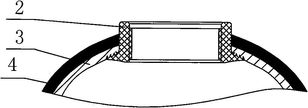
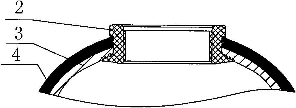
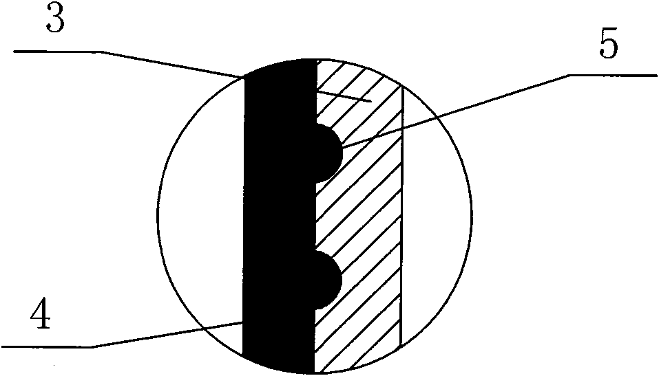
[0023] Such as figure 1 As shown, the present invention includes a base 1 for fixing the bottom, an inner tank 3, a threaded joint 2 fixedly connected at the neck of the inner tank 3 top, and a glass fiber winding layer wrapped outside the inner tank 3 and protecting the inner tank 3 4. The connection method between the liner 3 and the glass fiber winding layer 4 is bonding. In practical applications, the threaded interface 2 can also be arranged at the neck of the inner tank 3 bottom. Such as image 3 , Figure 5 As shown, the outer wall of the threaded interface 2 is correspondingly provided with an annular mosaic structure 7 for inlaying and fixing the end of the glass fiber winding layer 4 and a limiting protrusion preventing the threaded interface 2 from retracting into the glass fiber winding layer 4 . Wherein, the position-limiting protrusion is an annular protrusion 6 arranged on the upper part of the threaded interface 2, and the annular protrusion 6 is integrated...


PUM


Abstract

The invention discloses a fiberglass coated water container which includes an inner liner, a thread interface fixedly connected at the neck of the top part or the bottom part of the inner liner as well as a fiberglass coated layer coated outside the inner liner to carry out pro+tection on the inner liner. An annular embedding structure used for embedding and fixing the end part of the fiberglass coated layer is correspondingly arranged on the outer wall of the thread interface. The fiberglass coated water container has a simple structure, is conveniently processed and manufactured, can reliably run for a long period and can effectively solve the hidden trouble problem existed in peeling off between the inner liner and the coated layer.

Description

technical field [0001] The invention relates to a pressure vessel, in particular to a glass fiber wound water vessel working under a certain pressure. Background technique [0002] Such as figure 2 As shown, the existing glass fiber-wound water container is composed of an inner tank 3, a threaded joint 2 on the top or bottom thereof, and a glass fiber winding layer 4 wound outside the inner tank 3. It is a water treatment device for treating water. water container. The liner is anti-leakage, but the pressure bearing capacity is low, and the glass fiber wound shell protects the liner from deformation and damage under internal pressure. In the actual use of the water container, with the rise and fall of the pressure, the entire pressure container will expand and shrink slightly. When the bonding strength between the winding layer and the inner tank does not reach the ideal situation or after the pressure container has been working for a long time, The winding layer will be ...

Claims


Application Information

Patent Timeline
Patent Type & Authority Patents(China)
IPC IPC(8): F16J12/00
Inventor 谷宏治寇静利牛国良张娴
Owner XIAN SUNWARD AEROSPACE MATERIAL CO LTD
Why Eureka
Try Eureka