
Illumination lamp for sweeping robot

A technology for cleaning robots and lighting lamps, applied in the field of robots, can solve problems such as insufficient brightness, inability to locally adjust the light and shade, and inability to adjust, and achieve the effect of improving overall brightness

Inactive Publication Date: 2009-02-04
申杰环境发展(上海)有限公司 +1
View PDF0 Cites 4 Cited by
  • Summary
  • Abstract
  • Description
  • Claims
  • Application Information

AI Technical Summary

Problems solved by technology

[0010] In order to solve the following problems: 1. When the cleaning robot inspects the pipeline, the light of the lighting lamp is too concentrated in the front area, and the light on the two sides is seriously insufficient, and the brightness of the light cannot be adjusted locally; 2. Generally speaking, in the pipeline , the brightness is far from enough; 3. The tone (color) is inaccurate, or cannot be adjusted; the present invention proposes the following technical solutions

Method used


Image

  • Illumination lamp for sweeping robot
  • Illumination lamp for sweeping robot
  • Illumination lamp for sweeping robot

Examples


Embodiment 1

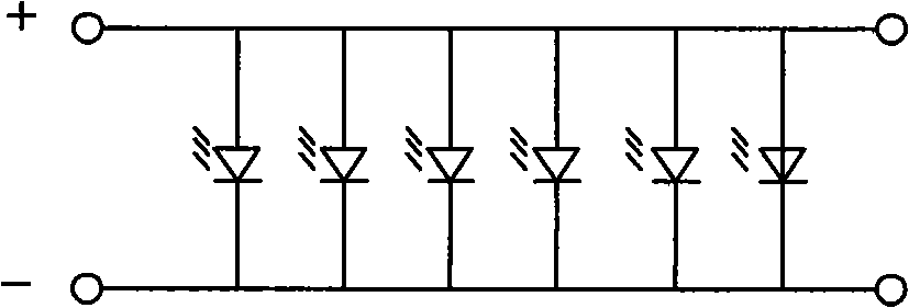
[0095] combine figure 1 ,Be explained.

[0096] This embodiment illustrates the situation that "the anode of one or more LED light-emitting diodes is connected to the positive line, and the negative pole of the LED light-emitting diode is connected to the negative line".

[0097] In the figure, "+" is the positive line, "-" is the negative line, and the electric energy of the DC power supply is provided by the circuit part of the robot. The positive line is connected to the positive pole of the DC power supply, and the negative line is connected to the negative pole of the DC power supply.

[0098] In the actual circuit, a current-limiting resistor is also connected in series with each LED light-emitting diode; a total current-limiting resistor can also be used in the circuit.

Embodiment 2

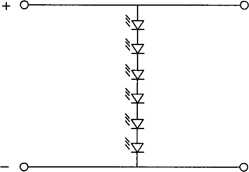
[0100] combine figure 2 ,Be explained

[0101] This embodiment illustrates the situation that "two or more LED light-emitting diodes are connected in series and straddled between the positive line and the negative line".

[0102] In the figure, "+" is the positive line, "-" is the negative line, and the electric energy of the DC power supply is provided by the circuit part of the robot.

[0103] The actual circuit also needs to connect a current limiting resistor in series.

[0104] The current-limiting resistor can be connected in series at the negative pole of the lowest LED light-emitting diode, or at other positions in the circuit. It can also be connected in series in the relevant circuit of the robot and then send the electric energy through the line.

Embodiment 3

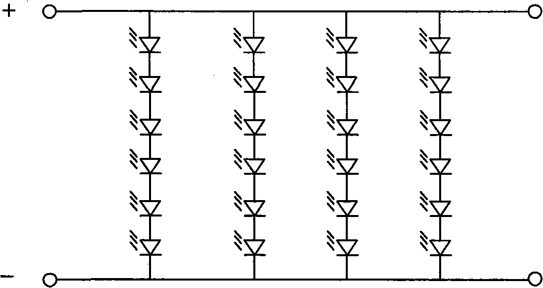
[0106] combine image 3 ,Be explained

[0107] This embodiment illustrates: 1. The situation that "two or more rows of LED light-emitting diodes are connected in series and connected between the positive line and the negative line". 2. "Series connection is the case where the negative pole of one LED light-emitting diode is connected to the positive pole of another LED light-emitting diode, and so on". 3. "The jumper is the LED light-emitting diodes after series connection, the positive pole of the first LED light-emitting diode is connected to the positive line, and the negative pole of the last LED light-emitting diode is connected to the negative line".

[0108] In the figure, "+" is the positive line, "-" is the negative line, and the electric energy of the DC power supply is provided by the circuit part of the robot.

[0109] In the actual circuit, a current limiting resistor is connected in series in each series circuit.

[0110] The current-limiting resistor can be c...


PUM


Abstract

The invention discloses a floodlight of a cleaning robot which relates to the technical field of robot. The following technical scheme is proposed for solving the problem that the beams of the floodlight are over-centralized on a right ahead area, and the like. The floodlight includes: a lamp holder, a lampshade, an LED, a current-limiting resistance (R), an anode circuit (+) and a cathode circuit (-); the invention is characterized in that: a) the LED is inserted on the dispersing surface of a mounting body; b) the connection mode of the LED is connected in series, and the like; the anode circuit (+) is one or two or more than two; c) a light transmission matter is arranged at the front surface of the illuminating end point of the LED and the light transmission matter is a glass matter or an organic glass matter or a light transmission plastic matter; besides, the light transmission matter is a colorless light transmission matter or a colored light transmission matter. The floodlight of a cleaning robot has the beneficial effects that: the beam of the floodlight is dispersed in the observing area and bright-dark adjusting can be carried out in a local area; the integral brightness in a pipeline is obviously improved; the dust can be more clearly displayed on a screen.

Description

technical field [0001] The invention relates to the technical field of robots, in particular to a lighting lamp for a cleaning robot. Background technique [0002] Due to the long-term use of central air conditioners, a lot of dust and garbage are deposited in the pipes, and the number of bacteria is serious, which is harmful to the human body. In order to clean the air-conditioning pipes and understand the hygienic conditions in the pipes, a cleaning robot is used, and the camera device that comes with the robot transmits the captured information to the control circuit with the computer as the core, and the operator is on the scene outside the pipes, through Monitor the display. [0003] Shooting in the air-conditioning duct, because it is in a dark environment, there are generally two ways, one is to shoot in the absence of lighting, the camera device uses the principle and method of infrared induction to shoot; the other is to provide lighting Under the circumstances, t...

Claims


Application Information

Patent Timeline
Patent Type & Authority Applications(China)
IPC IPC(8): F21V19/00F21V23/00F21V5/00F21V33/00B25J19/00F21W131/403F21Y101/02F21Y115/10
Inventor 毛立民陈升
Owner 申杰环境发展(上海)有限公司
Learn More