Heating stove

A heating stove and shell technology, applied in the field of heating stoves, can solve the problems of fuel obstruction, intelligent control, adjustment, high noise, etc., and achieve the effects of reducing power consumption, improving user comfort, and improving combustion efficiency.

Inactive Publication Date: 2010-06-16
王志潮
View PDF2 Cites 0 Cited by
  • Summary
  • Abstract
  • Description
  • Claims
  • Application Information

AI Technical Summary

Problems solved by technology

[0003] Although it is known that the combustion efficiency of the better pellet fuel heating stoves on the market has reached about 85%, and the average power consumption is about 150W, the structural design of these heating stoves is not reasonable enough, and the dust after the fuel burns out will continue. Deposited in the fuel box, it hinders the burning of newly filled fuel, increases the power consumption of the heating device, and also significantly reduces the combustion efficiency of the pellet fuel, which in turn makes the harmful components of the gas emitted by the heating furnace higher. At the same time, the noise is too loud and the average Power consumption is too high
[0004] On the other hand, the existing heating furnace is to set the working cycle of the charging machine by calculating the time required for the fuel that is delivered to the fuel box by the charging machine once to fully burn out, the working cycle of the charging machine and the fuel box The heating and burning speed of the internal fuel are fixed, and these technical parameters cannot be changed after the product leaves the factory, and these technical parameters are directly related to the temperature of the furnace when the heating furnace is working. Therefore, the working temperature of the furnace in the existing heating furnace is Single, it is impossible to intelligently control and adjust according to actual needs

Method used


Image

  • Heating stove
  • Heating stove
  • Heating stove

Examples


Embodiment Construction

[0034] The present invention will be further described in detail below in conjunction with the accompanying drawings and embodiments.

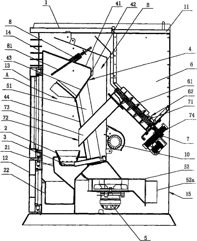
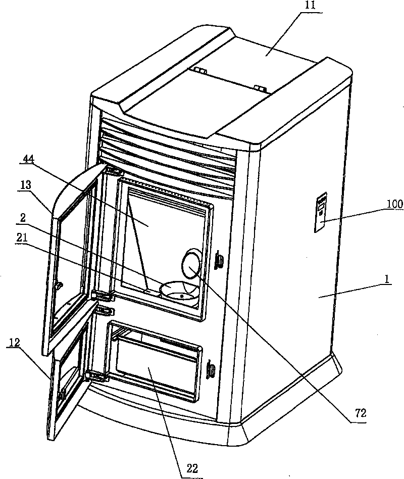
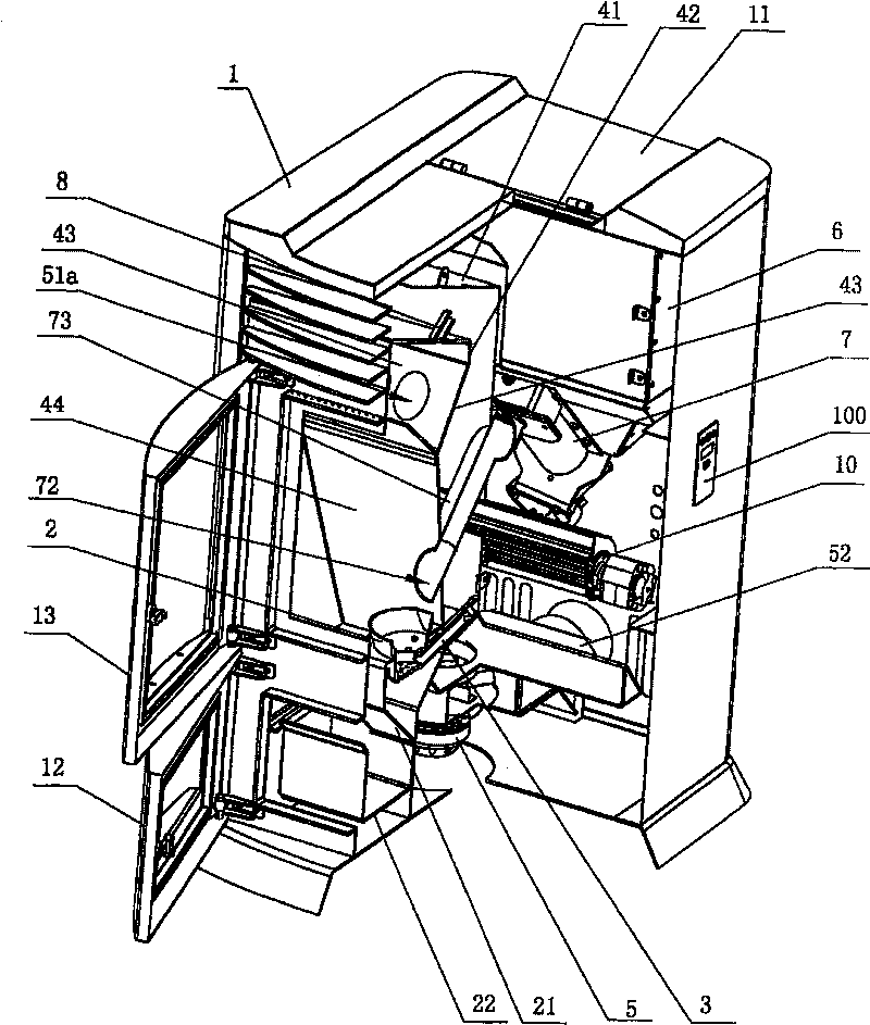
[0035] Such as Figure 1 to Figure 5 As shown, the heating furnace includes a housing 1 and the following components arranged in the housing 1:

[0036] A fuel box 2 arranged under the front part in the internal space of the casing 1, the fuel box 2 is limited by a base 21 with a limit hole;

[0037]A heating device 3 arranged at the bottom of the fuel cartridge 2, in this embodiment, the heating device 3 adopts a thermal resistance heating rod;

[0038] An ash hopper 22 arranged under the fuel box 2;

[0039] A partition plate 4 arranged on the top and rear side of the fuel box 2, the partition plate 4 divides the space above the fuel box 2 into a furnace A, the partition plate 4 includes a top-to-bottom connected bottom inclined The first part 41, the third part 43 whose bottom is inclined to the front side, the fourth part 44 whose botto...


PUM


Abstract

The invention discloses a warming stove which comprises a housing , a fuel box arranged in the housing, a heating device arranged at the bottom of the fuel box, a division plate, a feed box and a feedmechanism below the feed box, wherein, the division plate comprises following parts which are connected from top to bottom: a first part with the bottom inclining downwards, a third part with the bottom inclining forwards, a fourth part with the bottom inclining backwards and a second part connecting the first part and the third part; wherein, the third part is provided with openings, the bottomof the fourth part is positioned at the rear side of the fuel box, and a row of smoke exhaust fans are arranged at the lower part inside the housing, the smoke exhaust fans are provided with smoke suction pipes at the rear side of the fourth part in the division plate, the air inlets of the smoke suction pipes are communicated with the openings of the third part in the division plate, and the smoke exhaust fans are provided with smoke exhaust pipes with the end parts towards the rear part of the housing. Compared with the prior art, the warming stove can effectively improve combustion efficiency of the fuels, can reduce power consumption and noise, and can effectively lower the discharge amount of harmful gas.

Description

technical field [0001] The invention relates to a heating furnace, in particular to a heating furnace using granular fuel. Background technique [0002] Because the original fireplace and other heating stoves need to be manually taken care of, and fuel needs to be added in time, there are certain safety hazards, which bring some inconvenience to people, and the most important point is that more heat of this kind of heating stove is directly from the Flue loss, resulting in waste of energy, and poor heating effect. As a result, a heating stove with automatic feeding, sustainable combustion and high heat utilization rate evolved from the original fireplace came into being. Because it is easy to use, unattended, safe and reliable, some can even be moved, increasing Flexibility of use, and favored by consumers in general, as the patent No. is ZL00221979.4 (announcement number is CN2462247Y) Chinese utility model patent " particle fuel heating stove " just discloses such a kind ...

Claims


Application Information

Patent Timeline
Patent Type & Authority Patents(China)
IPC IPC(8): F23B40/02F23N1/00F23N5/02
Inventor 王志潮
Owner 王志潮
Why Eureka
Try Eureka