Bus connecting device for switch equipment and bus connecting method thereof

A technology of switchgear and connection device, applied in the field of bus connection device for switchgear and its bus connection, can solve the problems of increasing time, energy and cost, etc.

Inactive Publication Date: 2009-02-11
LSIS CO LTD
View PDF0 Cites 4 Cited by
  • Summary
  • Abstract
  • Description
  • Claims
  • Application Information

AI Technical Summary

Problems solved by technology

Therefore, the time, effort and cost required t

Method used


Image

  • Bus connecting device for switch equipment and bus connecting method thereof
  • Bus connecting device for switch equipment and bus connecting method thereof
  • Bus connecting device for switch equipment and bus connecting method thereof

Examples


Embodiment Construction

[0050] A detailed description will now be given of a bus connection device for a switchgear and a bus connection method thereof according to an embodiment of the present invention, an example of which will be explained with reference to the accompanying drawings.

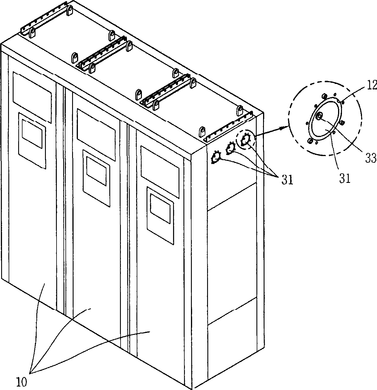
[0051] Such as Image 6As shown, the switchgear is provided with a plurality of panels 110 arranged in a row to perform various functions such as receiving power and supplying power to loads, relaying and calculating the main circuit bus, separating the main circuit bus, and in the case of dual bus The connection function of the bus. The panels 110 are electrically connected to each other at the upper interior of the panels 110 through the bus connection device 120 of the switchgear according to an embodiment of the present invention.

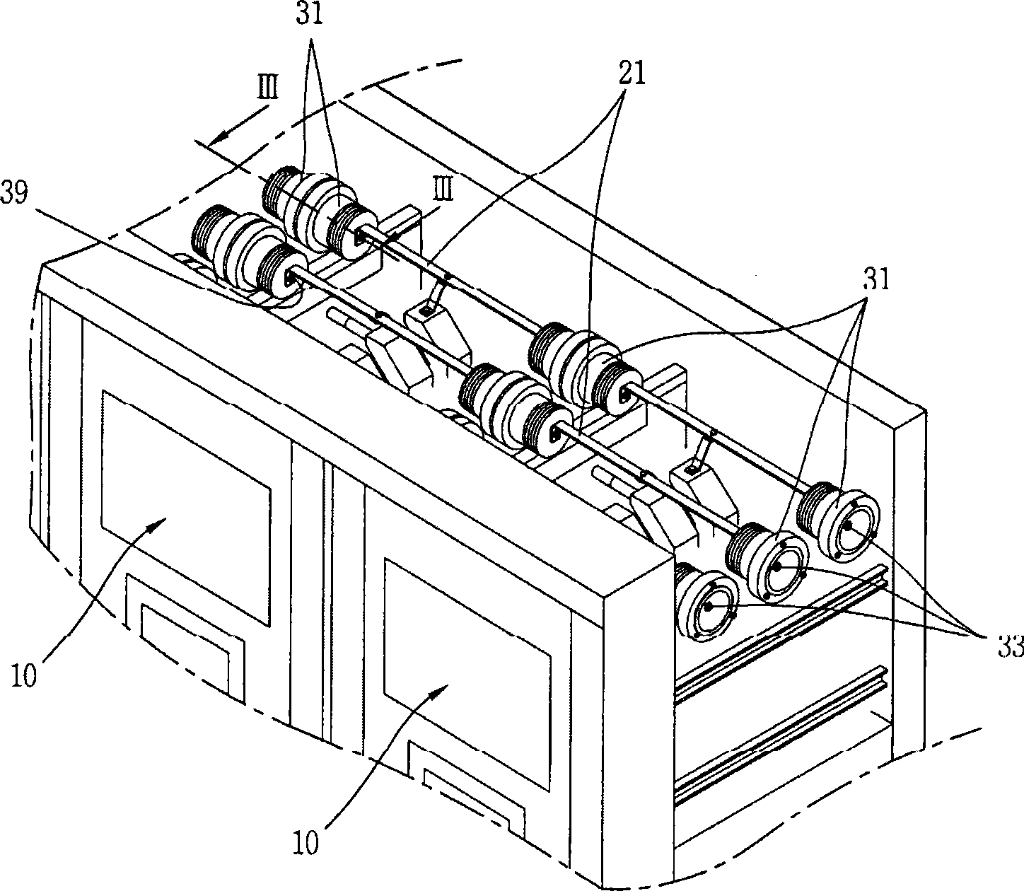
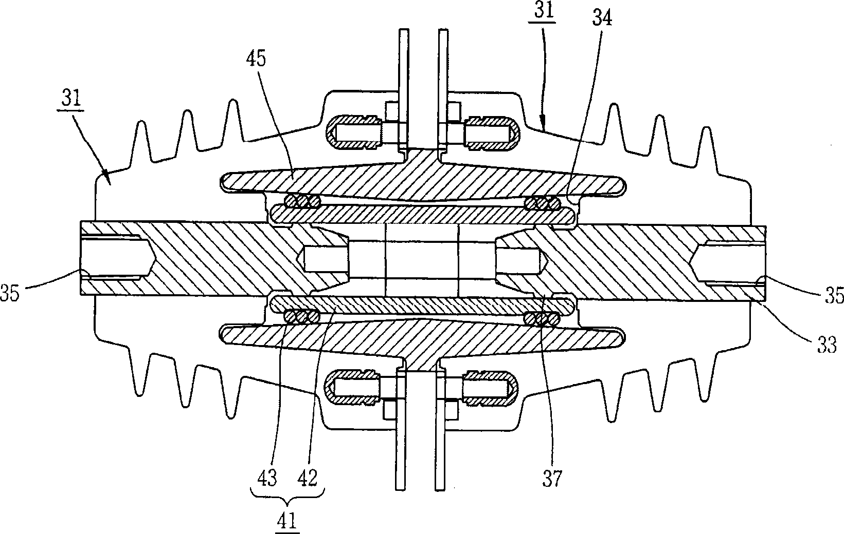
[0052] Figure 7 and Figure 8 As shown, the bus connection device 120 of the switchgear includes a connection module 121, and the connection module 121 includes a first conductor 1...


PUM


Abstract

A bus connection device for switch device comprises a connection module with a first conductor, a second conductor connected with the first conductor and a solid coating part for covering the outer surfaces of the first conductor and the second conductor; a bus with a conductor and a solid coating part for covering the outer surface of the conductor and conductively inserted between the two opposite connection modules; and an insulation tube for covering the connection module and the connection part of the bus. Thus the installation and maintenance of the board can be quickened and facilitated and the insulation material (such as oil or sulphur hexafluoride) can be prevented from being used.

Description

technical field [0001] The present invention relates to a bus connection device for a switchgear and a bus connection method thereof, and more particularly, to a bus connection device for a switchgear capable of speeding up and facilitating an assembly process between panels, and a bus connection method thereof. Background technique [0002] Such as figure 1 As shown, the switchgear is provided with a plurality of panels 10 arranged in a row. On the inner side of the upper part of each panel 10, as figure 2 As shown, the bus bars 21 for electrically connecting each panel 10 are arranged in such a direction that the panels 10 are arranged in a row to be in surface contact with each other. Sulfur hexafluoride (SF 6 ) gas is filled as an insulating material in the inner space where the bus bar 21 is provided. Through holes 12 are formed on both side walls of each panel 10 , and each through hole 12 is sealed by a sleeve 31 . [0003] The bushing 31 is formed as an insulat...

Claims


Application Information

Patent Timeline
IPC IPC(8): H02B1/20H01R4/48H01R13/18H01R4/70
CPCH02B13/005H01H31/02H02B13/035H02G5/00
Inventor 李在杰
Owner LSIS CO LTD
Why Eureka
Try Eureka