Chemical vapor deposition apparatus for flat display

A chemical vapor deposition, flat-panel display technology, applied in gaseous chemical plating, instruments, optics, etc., can solve problems such as bad, structural damage, impact, etc.

Inactive Publication Date: 2009-02-18
SFA ENG CORP
View PDF1 Cites 0 Cited by
  • Summary
  • Abstract
  • Description
  • Claims
  • Application Information

AI Technical Summary

Problems solved by technology

[0008] However, in a typical chemical vapor deposition apparatus, during a deposition process, when a process gas flows in and a high-frequency power is applied in a certain state, parasitic plasma is generated in the gas inlet part 1, so the gas inlet part 1 Internal and connected structures can be damaged and particles can be generated which directly have a negative impact on the processing results

Method used


Image

  • Chemical vapor deposition apparatus for flat display
  • Chemical vapor deposition apparatus for flat display
  • Chemical vapor deposition apparatus for flat display

Examples


Embodiment Construction

[0020] The drawings attached to the present invention are used to explain the preferred embodiments of the present invention and the objectives achieved so that its advantages can be easily understood. Hereinafter, the present invention will be explained in detail of its preferred embodiments by referring to the accompanying drawings. Reference numbers in the drawings represent components.

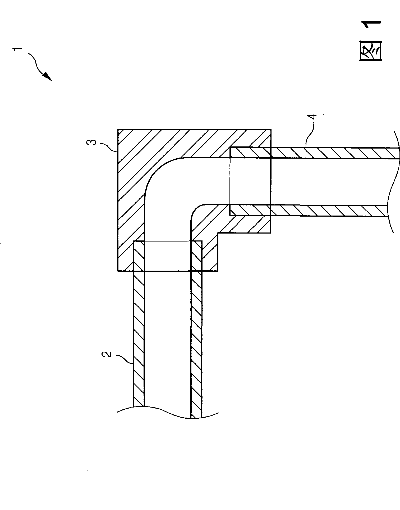
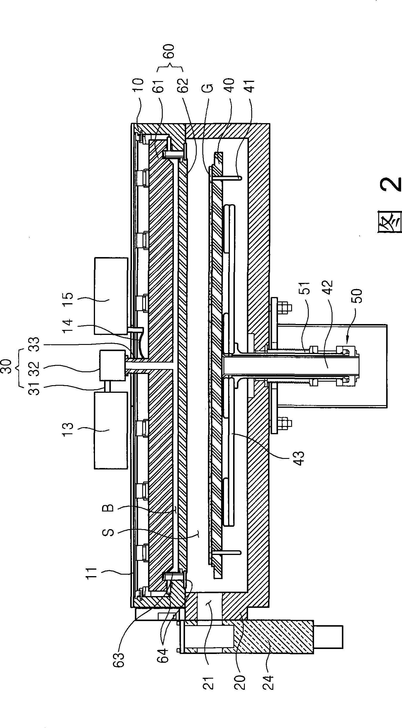
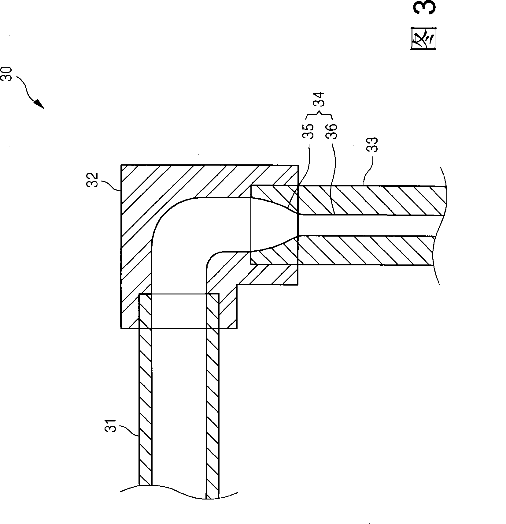
[0021] 2 is a cross-sectional view of a chemical vapor deposition apparatus for a flat panel display according to an embodiment of the present invention. 3 is a cross-sectional view of a gas inlet part according to an embodiment of the present invention. FIG. 4 is a schematic diagram of Paschen Curve.

[0022] Please refer to FIG. 2, the chemical vapor deposition apparatus for flat panel displays according to the present invention includes an upper reaction chamber 10 and a lower reaction chamber 20 (in the upper reaction chamber 10 and the lower reaction chamber 20, the deposition proce...


PUM


Abstract

The invention relates to a chemical vapor deposition apparatus for a flat display comprising a reaction chamber for performing a deposition processing to a substrate, an air inlet tube for injecting processing air into the reaction chamber and an air supplying tube connected to the air inlet tube and for guiding the processing air flowing to the air supplying tube. In the chemical vapor deposition apparatus, a parasitic electric slurry generation prevention part is located in the air inlet tube and prevents the parasitic electric slurry from generating in the air supplying tube through increasing the pressure of the air supplying tube during the deposition processing.

Description

technical field [0001] What the present invention relates to is a kind of chemical vapor deposition device for flat panel display, what relate in particular is a kind of chemical vapor deposition device for flat display, it is by reducing the conductance (conductance) of gas inlet pipe (gas inlet pipe) ) to prevent the generation of parasitic plasma in the gas feed-through pipe. Background technique [0002] Due to the rapid development of semiconductor electronic display companies, flat panel displays (FDP) are widely used. Flat panel displays are thinner and thinner than cathode ray tube displays (CRTs), which are mainly used in televisions or computer monitors, and include liquid crystal displays (LCDs), plasma display panels (PDPs), and organic light emitting diodes (OLEDs). [0003] Liquid crystal display is a kind of flat panel display, which is formed by injecting liquid crystal (between solid state and liquid state) as an intermediate substance between two thin uppe...

Claims


Application Information

Patent Timeline
Patent Type & Authority Applications(China)
IPC IPC(8): C23C16/455C23C16/52
CPCC23C16/455G02F1/13H01L21/205H01L21/3065
Inventor 朴相泰李相琝张哲钟
Owner SFA ENG CORP
Why Eureka
Try Eureka