A kind of thermal interface material and preparation method thereof

A thermal interface material, one-sided technology, applied in heat exchange materials, chemical instruments and methods, semiconductor devices, etc., can solve the large difference in thermal deformation between organic matter and thermally conductive particles, the decrease in thermal conductivity of composite materials, and the small thermal expansion coefficient of thermally conductive particles. and other problems to achieve the effect of avoiding the decrease of heat conduction capacity, small difference in thermal deformation and stable performance

Active Publication Date: 2022-01-18
SHENZHEN TAOTAO TECH CO LTD
View PDF13 Cites 0 Cited by
  • Summary
  • Abstract
  • Description
  • Claims
  • Application Information

AI Technical Summary

Problems solved by technology

[0004] The purpose of the present invention is to provide a thermal interface material for use and a preparation method thereof, so as to solve the problem that the thermal expansion coefficient of heat-conducting silicone grease heat-conducting particles in the prior art is small, the thermal expansion coefficient of organic matter is large, and the thermal deformation difference between organic matter and heat-conducting particles is large. , leading to the problem that the thermal conductivity of the composite material decreases due to the formation of many voids or holes in the interior of the peeling during use.

Method used


Image

  • A kind of thermal interface material and preparation method thereof
  • A kind of thermal interface material and preparation method thereof
  • A kind of thermal interface material and preparation method thereof

Examples


Embodiment Construction

[0031] In order to make the object, technical solution and advantages of the present invention clearer, the present invention will be further described in detail below in conjunction with the accompanying drawings and embodiments. It should be understood that the specific embodiments described here are only used to explain the present invention, not to limit the present invention.

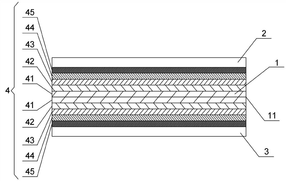
[0032] figure 1 An embodiment of the thermal interface material of the present invention for a heat sink is shown, see figure 1 , in this embodiment, the thermal interface material includes a base material layer 1 , a first contact layer 2 , a second contact layer 3 and a doping material 4 .

[0033] Wherein, the base material layer 1 is made of a material with a positive thermal expansion coefficient or a material with a negative thermal expansion coefficient, and the first contact layer 2 covers one side of the base material layer 1 and is in contact with a heat source; the second contact layer ...


PUM

PropertyMeasurementUnit
thicknessaaaaaaaaaa
thicknessaaaaaaaaaa
shear strengthaaaaaaaaaa

Abstract

The invention discloses a thermal interface material and a preparation method thereof, wherein the thermal interface material is used to transfer heat generated by a heat source to a radiator, and the thermal interface material includes a base material layer, a first contact layer, a second contact layer and doped material. The base material layer is made of a material with a positive thermal expansion coefficient or a material with a negative thermal expansion coefficient. The first contact layer covers one side of the base material layer and is in contact with the heat source; the second contact layer covers the other side of the base material layer and is in contact with the heat sink; The thermal expansion coefficient of the dopant material is opposite to that of the base material layer, and the concentration of the dopant material increases from the center plane of the base material layer to the first contact layer and the second contact layer respectively in preset gradients. In the present invention, the concentration of the dopant material is gradually increased in a predetermined gradient to ensure that the difference in thermal deformation between the organic matter and the heat-conducting particles in the thermal interface material is small, avoiding the peeling of the organic matter and the heat-conducting particles to form holes that lead to a decrease in thermal conductivity, and ensuring the stable performance of the thermal interface material.

Description

technical field [0001] The invention relates to the technical field of heat dissipation materials, in particular to a thermal interface material for a radiator and a preparation method thereof. Background technique [0002] The current thermal interface materials mainly use thermal conductive silicone grease, which is commonly known as heat dissipation paste. Thermal conductive silicone grease uses organic silicone as the main raw material, and adds granular materials with excellent heat resistance and thermal conductivity to make a thermally conductive silicone grease compound. It is used for heat conduction and heat dissipation of electronic components such as power amplifiers, transistors, electronic tubes, and CPUs, so as to ensure the stability of electrical performance of electronic instruments and meters. [0003] However, the thermal expansion coefficient of the heat-conducting silicone grease heat-conducting particles is small, the thermal expansion coefficient of t...

Claims


Application Information

Patent Timeline
Patent Type & Authority Patents(China)
IPC IPC(8): C09K5/14H01L23/373
CPCC09K5/14H01L23/3735H01L23/3738
Inventor 李毅刘建国吴沙欧
Owner SHENZHEN TAOTAO TECH CO LTD
Why Eureka
Try Eureka