Large area light alloy micro-arc oxidization surface processing method and apparatus

A micro-arc oxidation and surface treatment technology, applied in the field of metal surface treatment, can solve the problems of difficult to realize automatic continuous treatment, loss of modification function of oxide film, inability to realize treatment method, etc., to save energy and improve the utilization rate of electric energy. , a wide range of effects

Inactive Publication Date: 2009-02-18
THIXOMAG TECHNOLOGH WUHU
View PDF1 Cites 10 Cited by
  • Summary
  • Abstract
  • Description
  • Claims
  • Application Information

AI Technical Summary

Problems solved by technology

Its disadvantages are: firstly, in production and use, it is necessary to assemble the cathode device and the anode workpiece, and use an adhesive to bond and fix the cathode device on the area of ​​the workpiece to be processed. Such a treatment method has low production efficiency and It is not easy to realize automatic continuous processing; secondly, because the cathode electrode is bonded to the anode workpiece, such a treatment method cannot be realized on the surface of the complex workpiece; finally, because the workpiece undergoes micro-arc oxidation treatment, a large amount of heat is generated, resulting in The temperature of the electrolyte rises rapidly in a short period of time, even causing the electrolyte to boil, while the temperature of the solution in the micro-arc oxidation treatment cannot exceed 50°C, otherwise the oxide film of the workpiece will be strongly broken down, and the phenomenon of "ablation" will occur, and the oxide film will lose its modification. Function

Method used


Image

  • Large area light alloy micro-arc oxidization surface processing method and apparatus
  • Large area light alloy micro-arc oxidization surface processing method and apparatus
  • Large area light alloy micro-arc oxidization surface processing method and apparatus

Examples


Embodiment Construction

[0043]Referring to the accompanying drawings, through the description of the embodiments, the specific implementation of the present invention, such as the shape, structure, mutual position and connection relationship between the various parts, the function and working principle of each part, and the manufacturing process And the method of operation and use, etc., are described in further detail to help those skilled in the art have a more complete, accurate and in-depth understanding of the inventive concept and technical solution of the present invention.

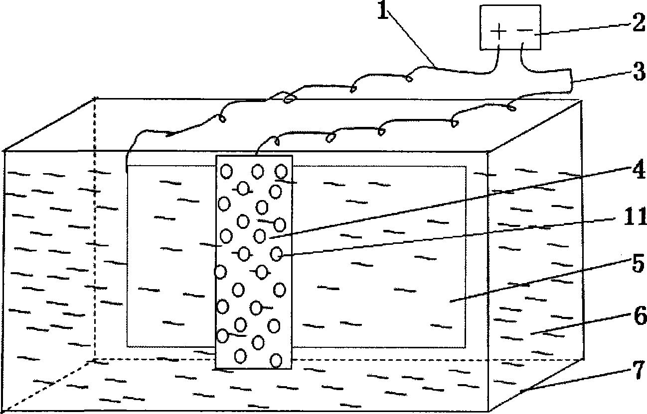
[0044] Such as figure 1 The structure adopted in the present invention expressed is a device for realizing a large-area light alloy micro-arc oxidation surface treatment method, which device includes an electrolyte tank 7, a micro-arc oxidation electrolyte 6, a cathode electrode device 4, an anode workpiece 5, and a cathode Device wire 3, anode workpiece wire 1 and micro-arc oxidation power supply 2.

[0045] In order to...


PUM

PropertyMeasurementUnit
thicknessaaaaaaaaaa
lengthaaaaaaaaaa
widthaaaaaaaaaa

Abstract

The invention discloses a microarc oxidation surface treatment method for treating a large-area light alloy and a corresponding device for implementing the method. The method includes the following steps: arranging a cathodal electrode device with a surface area smaller than the surface area of an anodic workpiece on a local area of a large-area anodic workpiece, so as to process microarc oxidation surface treatment to the local areas of the anodic workpiece; and adjusting the position of the cathodal electrode device relative to the anodic workpiece and gradually enabling the cathodal electrode device to have reaction with all the areas on the surface of the anodic workpiece. All the areas have the same degree of reaction, so the whole surface of the anodic workpiece can be processed with microarc oxidation treatment. The technical proposal is adopted to have the advantage that when processing microarc oxidation surface treatment to different areas of the large-area light alloy, the position of the relative electrode with respect to the anodic workpiece can be adjusted freely. The device is convenient to install and disassemble. The invention has wide application range and can save energy and reduce cost, thus effectively reducing the production cost.

Description

technical field [0001] The invention belongs to the technical field of metal surface treatment, in particular, the invention relates to a surface treatment method of large-area light alloy micro-arc oxidation. Furthermore, the invention also relates to a device for carrying out such a method. Background technique [0002] Light metals and their alloys have many significant advantages. For example, small specific gravity, high specific strength, good rigidity, excellent thermal conductivity and electrical conductivity, etc. Light alloys play a pivotal role in modern industrial applications. In particular, people's consensus on energy saving, environmental protection, and lightweight has further increased the demand for light alloys and accelerated the research and development of light alloys. [0003] In modern industrial applications, aluminum alloy has become the second largest metal material after steel. Especially under the combined application of advanced forming tech...

Claims


Application Information

Patent Timeline
Patent Type & Authority Applications(China)
IPC IPC(8): C25D11/02
Inventor 徐章跃赵之良何明修
Owner THIXOMAG TECHNOLOGH WUHU
Why Eureka
Try Eureka