Glass fiber wall cloth edge-cutting electronic error-correcting apparatus
A deviation correction device and glass fiber wall technology, applied in the field of deviation correction devices, can solve the problems of small friction coefficient, inaccurate deviation correction, weak deviation correction function, etc., achieve accurate cutting, improve automation, improve product quality and work efficiency Effect
- Summary
- Abstract
- Description
- Claims
- Application Information
AI Technical Summary
Problems solved by technology
Method used
Image
Examples
Embodiment 1
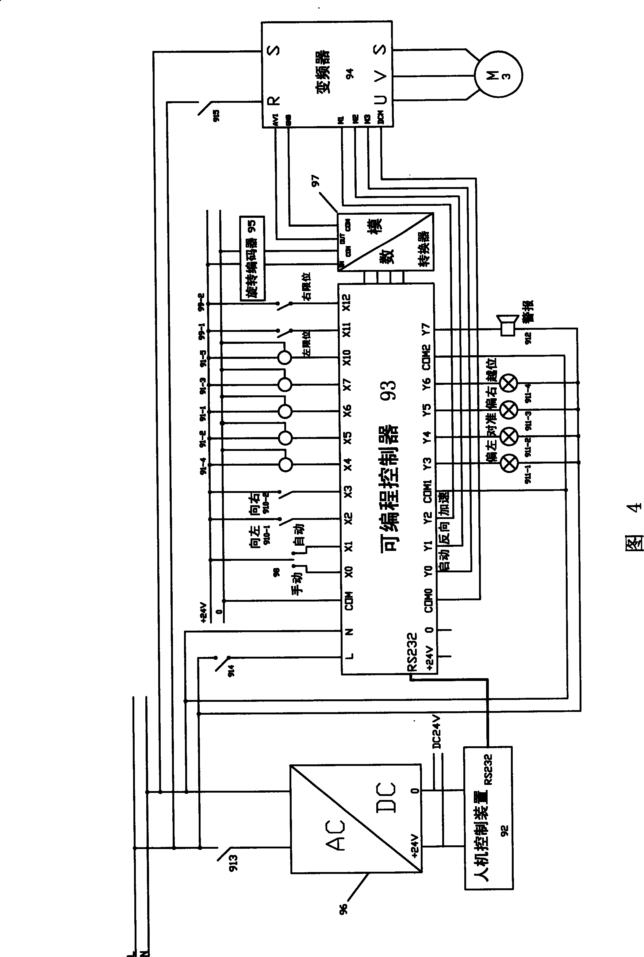
[0047] See Figure 1 to Figure 3 , In this embodiment, the glass fiber wall trimming electronic deviation correction device is composed of a control system and an execution system.
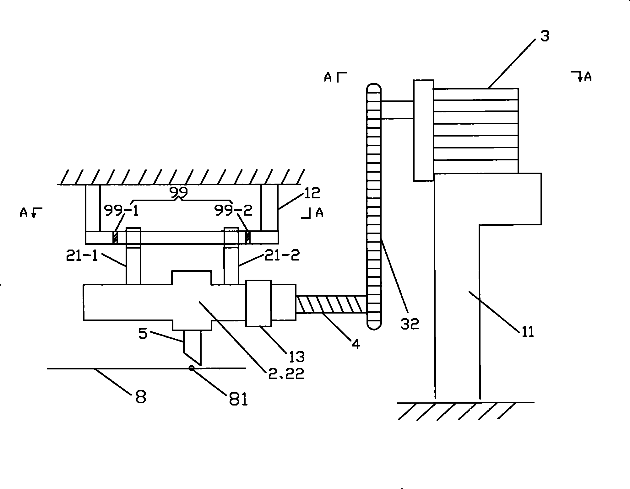
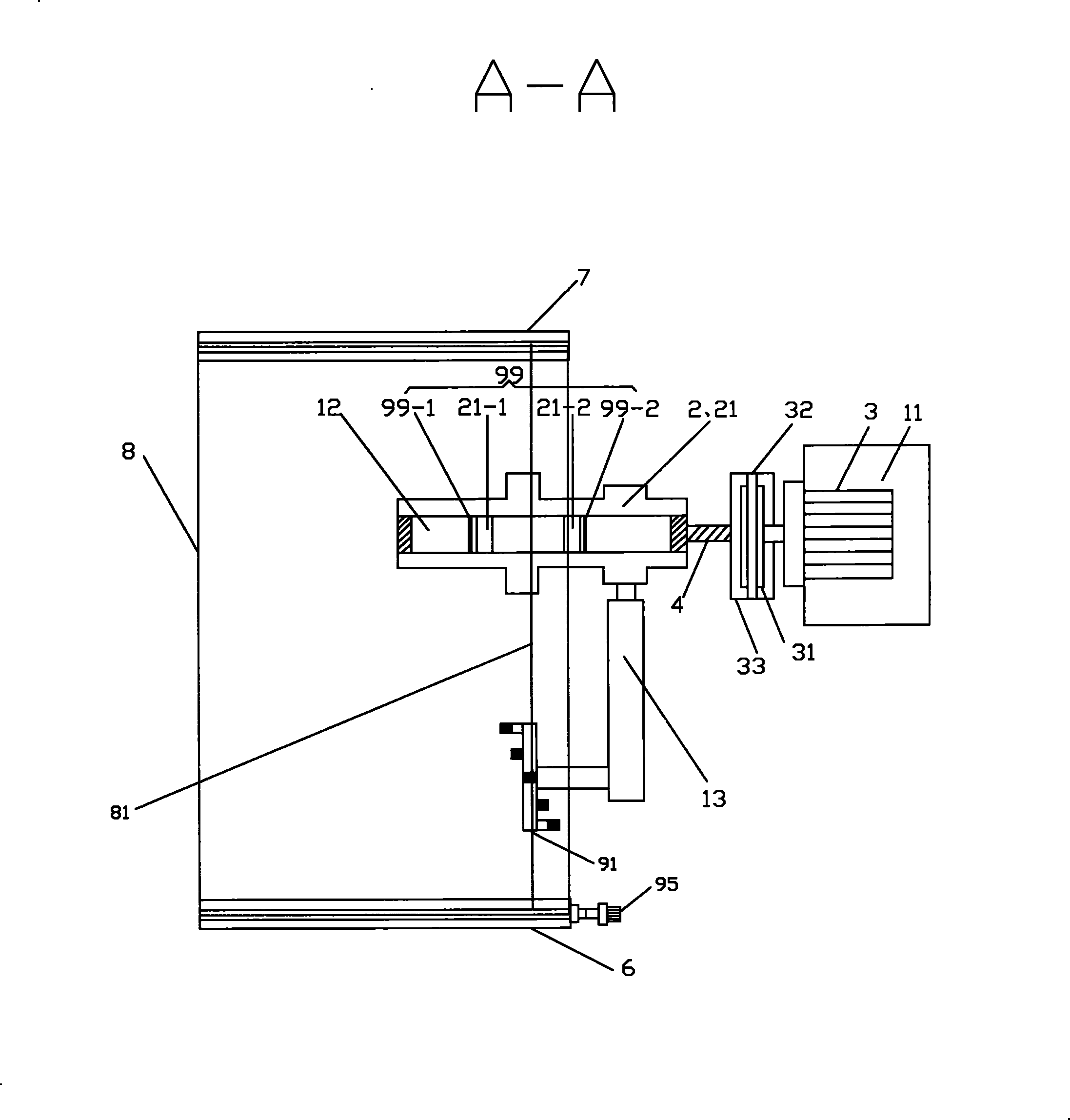
[0048] See figure 1 and figure 2 , The execution system includes an execution motor frame 11 , a slider frame 12 , a sensor frame 13 , a knife frame 2 , an execution motor 3 , a screw rod 4 and a cutter 5 .
[0049] In the execution system, the actuator frame 11 and the slider frame 12 are fixed structural parts during use. The specific structure is: the frame of the glass fiber wall cloth cutting machine is fixed with a gantry-shaped installation frame, the slide bar frame 12 is fixed on the installation frame and is located above the wall cloth 8, and the executive motor frame 11 is also fixed on the glass fiber wall cloth cutting machine. machine rack. There is no direct connection between the slide bar frame 12 and the actuator frame 11, and the slide bar frame 12 is arranged horizontally...
Embodiment 2
[0080] See image 3 and Figure 4, and see figure 1 and figure 2 , all the other are identical with embodiment 1, and difference is: the color mark sensor 91 in the present embodiment is 2 (just need to put figure 2 The left second color mark sensor 91-4, the middle color mark sensor 91-1 and the right side second color mark sensor 91-5 can be removed), and the two color mark sensors are the left side second color mark sensors arranged according to the left and right levels. A color mark sensor 91-2 and the first color mark sensor 91-3 on the right side. The distance between the two color mark sensors is 1.25mm. When the color line 81 is located in the middle of the left first color mark sensor 91-2 and the right first color mark sensor 91-3, it means that the trimming position is accurate. When the left first color mark sensor 91-2 detects the color line 81 signal, it means that the wall covering has shifted to the left by 0.625mm during the travel, so at this time, unde...
Embodiment 3
[0082] See image 3 and Figure 4, and see figure 1 and figure 2 , all the other are the same as Embodiment 1, the difference is: there are 3 color mark sensors 91 in the present embodiment (only need figure 2 The second color mark sensor 91-4 on the left side and the second color mark sensor 91-5 on the right side can be removed), and the 3 color mark sensors are to set the first color mark sensor 91-2 on the left side according to the level of left, middle and right , the middle color mark sensor 91-1 and the first color mark sensor 91-3 on the right side. The distance between two adjacent color mark sensors is 1.25mm. When the middle color mark sensor 91-1 detects the color line 81, it means that the edge trimming position is accurate; when the left first color mark sensor 91-2 detects the color line 81, it means that the wall covering has shifted to the left during travel Therefore, under the control of the programmable controller 93, the cutting knife 5 moves to the ...
PUM
 Abstract
Description
Claims
Application Information
 - R&D
- Intellectual Property
- Life Sciences
- Materials
- Tech Scout
- Unparalleled Data Quality
- Higher Quality Content
- 60% Fewer Hallucinations
Browse by: Latest US Patents, China's latest patents, Technical Efficacy Thesaurus, Application Domain, Technology Topic, Popular Technical Reports.
© 2025 PatSnap. All rights reserved.Legal|Privacy policy|Modern Slavery Act Transparency Statement|Sitemap|About US| Contact US: help@patsnap.com


