
Engine braking device and method

An engine braking and engine technology, applied in engine control, engine components, machine/engine, etc., can solve the problems of large size of eddy current retarder, failure of brake action, and failure of hydraulic medium to be updated, and achieve a good market. Foreground, simple control strategy, simple control effect

Inactive Publication Date: 2009-02-18
CHERY AUTOMOBILE CO LTD
View PDF0 Cites 17 Cited by
  • Summary
  • Abstract
  • Description
  • Claims
  • Application Information

AI Technical Summary

Problems solved by technology

[0003] The eddy current retarder is one of them, but the eddy current retarder uses electromagnetic force to decelerate the car, a large amount of current will pass through the coil, the coil may burn out, and the retarder will fail
In addition, the eddy current requires a large number of coils to achieve the purpose of electromagnetic resistance, so the eddy current retarder is large in size and mass, and increases the quality of the transmission system, so that a large number of small cars cannot be retarded by the eddy current. engine matching, which requires an engine-assisted braking device
[0004] As an auxiliary braking device, engine braking requires small volume, light weight, compact structure, short response time, low cost, high braking power and flexible control. However, in the structure of the engine brake, part of the hydraulic medium is in the hydraulic pipeline. During the reciprocating movement, the hydraulic medium cannot be renewed, and only the leaked hydraulic medium is replenished in each cycle. Air bubbles inevitably exist during the installation and use of the brake, which may make the established hydraulic pressure not reach the pre-designed The value of the value makes the action of the brake invalid

Method used


Image

  • Engine braking device and method
  • Engine braking device and method
  • Engine braking device and method

Examples


Embodiment Construction

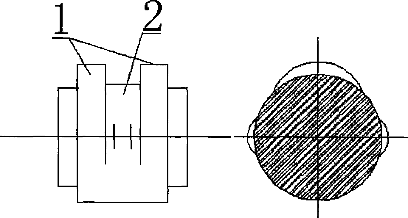
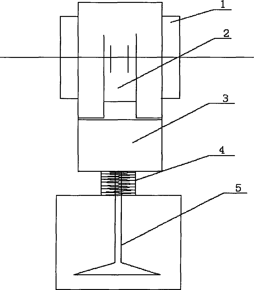
[0030] According to the attached figure 2 , 3 and 5 describe the braking device of the present invention in detail, which is a preferred embodiment among the various implementations of the present invention.

[0031] A device for realizing engine braking according to the present invention includes an engine exhaust valve 5, a valve spring 4, an exhaust cam, and a variable hydraulic tappet mechanism 3, and the variable hydraulic tappet mechanism 3 includes an inner cavity 8 , the outer cavity 9, the pin hole 6 located in the inner cavity and the positioning pin 7 that can move between the inner and outer cavity and insert into the pin hole, wherein the exhaust cam is a double-cam structure, consisting of an outer cam 1 and an inner cam 2, variable The hydraulic tappet mechanism 3 is located between the exhaust valve and the exhaust cam, which can realize the switching between the inner and outer cams. When the engine brake is not needed, the hydraulic system can apply pressur...


PUM


Abstract

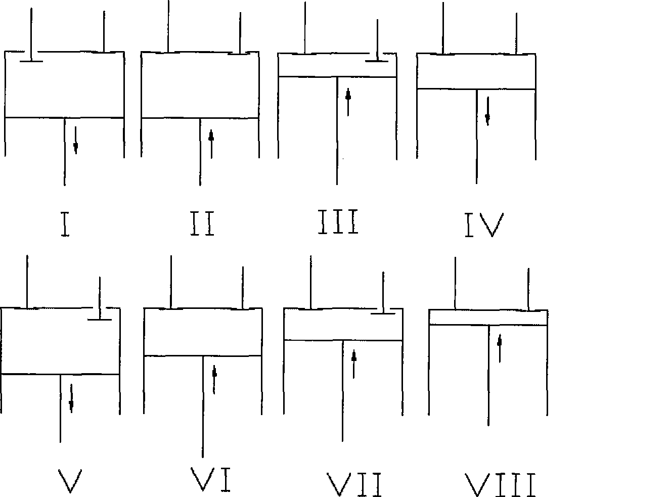
The invention relates to a device and a method for realizing the engine brake; the device comprises an engine exhaust valve, a valve spring, an exhaust cam and a variable hydraulic tappet mechanism; wherein, the exhaust cam is a double-cam structure composed of an outer cam and an inner cam; the variable hydraulic tappet mechanism is positioned between the exhaust valve and the exhaust cam and is able to realize the switching between the inner cam and the outer cam; the engine exhaust valve is controlled by the outer cam in the normal operating stage and controlled by the inner cam in the brake stage; according to the designed profile line of the inner cam, the exhaust valve is controlled to be opened in the late period of the compression stroke and during the expansion stroke to realize the engine brake effect. The device and the method for realizing the engine brake have the advantages of simple structure, easy control, high reliability, realizing the engine brake and particularly realizing the rapid brake of the diesel engine.

Description

technical field [0001] The invention relates to a device and method for realizing engine braking, in particular to a device and method for realizing diesel engine braking, belonging to the field of automobile engine braking. Background technique [0002] The power of modern cars is getting bigger and bigger, the load quality is getting heavier, the speed is getting higher and higher, and the friction loss inside the vehicle is getting smaller and smaller, which means that the deceleration ability of the vehicle itself is reduced, and only relying on the main force of the car itself The braking system has been difficult to meet the braking demand of the vehicle under the condition of high speed and heavy load. In order to ensure the safety performance of the vehicle, it is necessary to increase the auxiliary braking mechanism. [0003] The eddy current retarder is one of them, but the eddy current retarder uses electromagnetic force to decelerate the car, a large amount of c...

Claims


Application Information

Patent Timeline
IPC IPC(8): F02D13/04F01L13/06
Inventor 汤绪雯张华赵辉
Owner CHERY AUTOMOBILE CO LTD
Learn More