Fan filter screen unit and dust-free chamber

A fan filter and clean room technology, applied in the direction of pump components, ventilation systems, dispersed particle filtration, etc., can solve the problems of small fan filter unit coverage, short cycle dust particles, retention, etc., to reduce construction costs Effects on energy consumption, reduction of uneven cleanliness, and increase in circulating air volume

Inactive Publication Date: 2009-02-18
POWERCHIP SEMICON CORP
View PDF0 Cites 2 Cited by
  • Summary
  • Abstract
  • Description
  • Claims
  • Application Information

AI Technical Summary

Problems solved by technology

Although the turbulent flow clean room can significantly reduce the demand for the fan filter unit, however, the fan filter unit covers a small area and the circulating air volume is low, which will make the air flow only in the vertical direction, which will easily cause short circulation and dust particles in some areas phenomenon of retention
[0005] In general semiconductor factories, if the cleanliness or temperature of the clean room is not up to standard, it will seriously affect the operation of manufacturing process equipment and the yield of components
However, the cost of setting up and maintaining a clean room is high

Method used


Image

  • Fan filter screen unit and dust-free chamber
  • Fan filter screen unit and dust-free chamber
  • Fan filter screen unit and dust-free chamber

Examples


Embodiment Construction

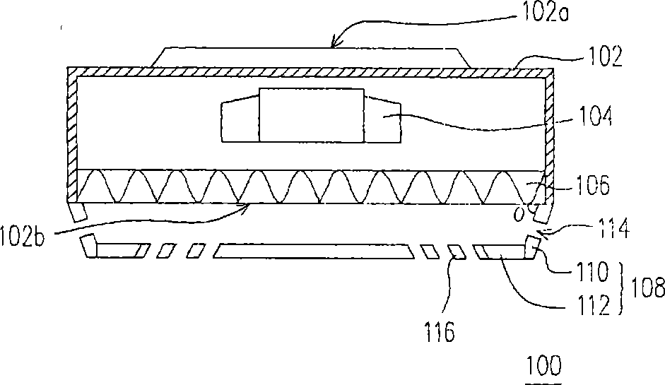
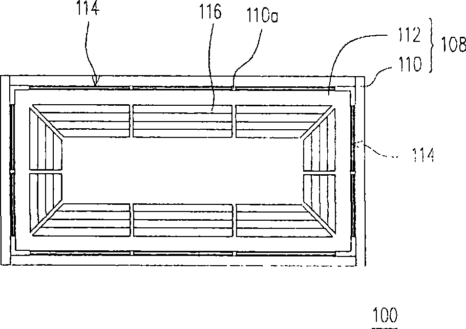
[0053] figure 1 is a schematic cross-sectional view of a fan filter unit according to an embodiment of the present invention. figure 2 is a schematic bottom view of a fan filter unit according to an embodiment of the present invention.

[0054] Please refer to figure 1 , the fan filter unit 100 includes a casing 102 , a fan 104 , a filter 106 and an induced airflow diffuser 108 . The casing 102 is, for example, a rectangular hollow cube, and the top and bottom of the casing 102 are through. The casing 102 has an air inlet 102a and an air outlet 102b, and the air inlet 102a and the air outlet 102b are arranged coaxially, for example. The air inlet 102a is, for example, disposed on the top of the casing 102 . The air outlet 102b is, for example, disposed at the bottom of the casing 102 .

[0055] The fan 104 is disposed inside the casing 102 and located between the air inlet 102a and the air outlet 102b. The shaft of the fan 104 is, for example, connected to a motor (not ...


PUM


Abstract

Disclosed is a fan filter screen unit which comprises a machine shell, a shell and an induction airflow dispersion plate; the machine shell includes a wind inlet and a wind outlet. The fan is arranged in the machine shell and between the wind inlet and the wind outlet. The induction airflow dispersion plate is arranged under the machine shell and comprises a faceplate and a frame. The faceplate is arranged under the wind outlet; the faceplate is provided with vanes which are arranged in the radial form. The frame is arranged between the machine shell and the faceplate. The frame is arranged around the periphery of the faceplate and connected with the faceplate. The frame is provided with a plurality of injection induction holes.

Description

technical field [0001] The present invention relates to a clean room device, and in particular to a structure of a fan filter unit (FFU). Background technique [0002] A clean room refers to an environment with a low pollution level, that is, to remove dust particles, chemical volatile gases, microorganisms and other pollutants in the air within a space range, and to control the indoor temperature, humidity, cleanliness, and indoor air quality. Conditions such as pressure, airflow velocity, and airflow distribution are controlled within a certain range of confined spaces. Usually, the clean room is the main production area in a semiconductor factory, where all the processing of semiconductor components takes place. Since the pollution of floating particles and dust in the air will have a great impact on the quality, reliability and yield of the components, in order to achieve the required benchmark, it is necessary to rely on the cooperation of many system equipment to main...

Claims


Application Information

Patent Timeline
IPC IPC(8): F04D29/70B01D46/00F24F3/16F24F7/06F24F13/08
Inventor 黄朝阳何照铭
Owner POWERCHIP SEMICON CORP
Why Eureka
Try Eureka