
Sonde system with gliding function

A radiosonde and functional technology, applied in the field of radiosonde systems, can solve the problems of high maintenance cost, high reliability, low cost, wide detection range, etc., so as to increase the detection range and blanking time, save the use cost and the detection range. wide effect

Inactive Publication Date: 2009-02-18
王爱喜
View PDF0 Cites 5 Cited by
  • Summary
  • Abstract
  • Description
  • Claims
  • Application Information

AI Technical Summary

Problems solved by technology

[0003] The disadvantages of the existing technology are: the conventional sounding process takes about 2 hours, the distance between the radiosonde and the flying point can reach more than 200km, the recovery of the radiosonde is very difficult, and it is easy for the radiosonde itself to fall freely to the ground damaged, so the current radiosonde is generally used for one-time use and will not be recycled; in addition, after the radiosonde balloon exploded at a height of 40km, the radiosonde fell to the ground freely, which is very easy to hurt people and animals; and because the radiosonde The airsonde is no longer recycled, and the batteries, electronic components, and metal equipment on it have caused a certain degree of pollution to the environment; the above three points have greatly limited the flying period, flying place and scope of use of the airsonde
The use of airplanes can solve the problem of airsonde recovery, but the airplane cannot rise to an altitude of 40km (limited by engine and aerodynamic conditions, the general flight altitude is <10km), take-off and landing require a site, the maintenance cost is too high, and the airplane itself Due to the limitation of reliability, it is unable to meet the multi-faceted requirements of the radiosonde for meteorological detection, so the meteorological departments at home and abroad still use the balloon-type radiosonde
[0005] In view of the above reasons, the existing airsondes cannot take into account the needs of 40km high-altitude detection, flying at any place, safe recovery, wide detection range, high reliability, and low cost.

Method used


Image

  • Sonde system with gliding function
  • Sonde system with gliding function
  • Sonde system with gliding function

Examples


Embodiment Construction

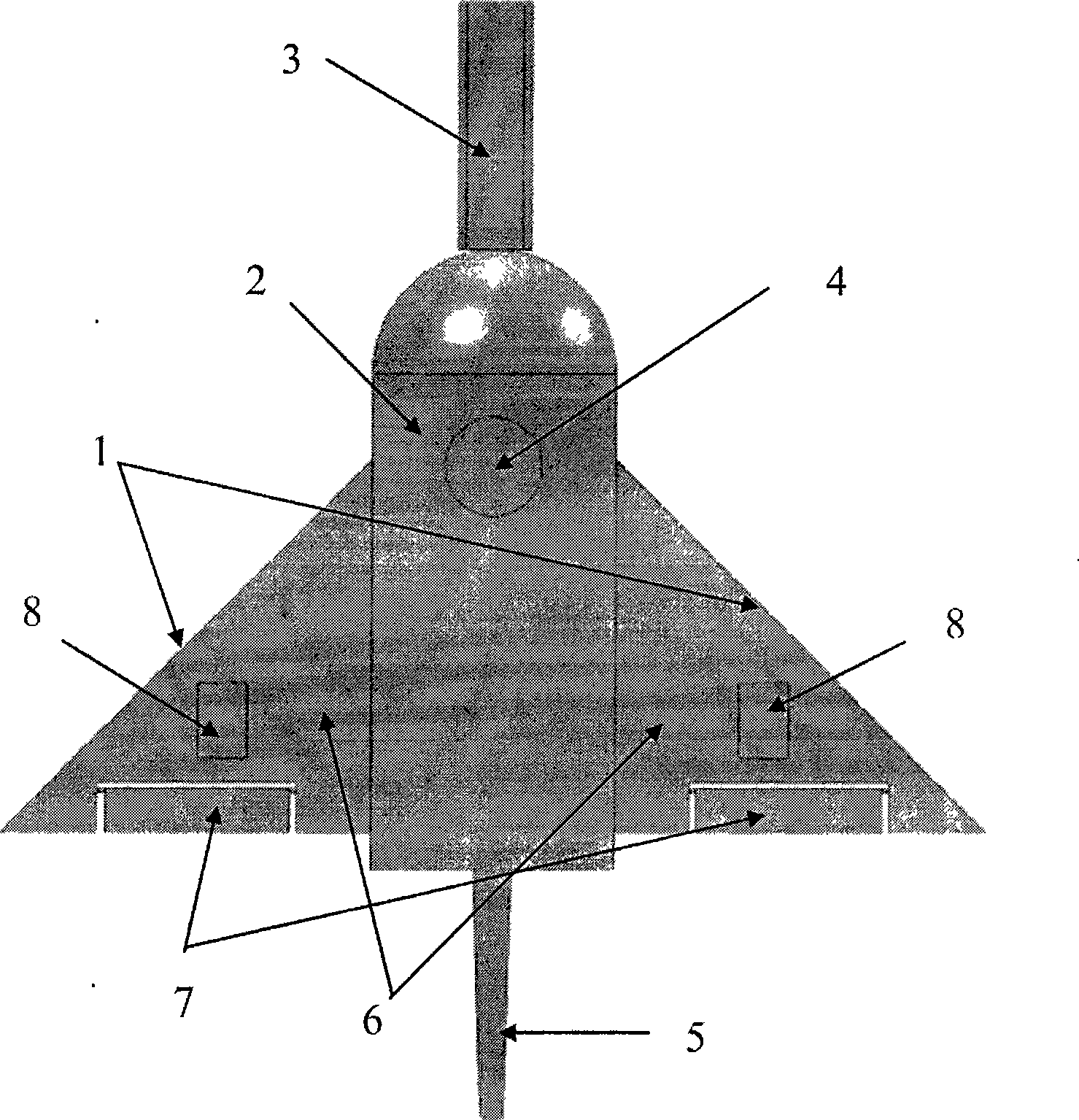
[0013] A radiosonde using the GPS system is used as an example for illustration. refer to figure 1 , a radiosonde system with gliding function shown in it is composed of a gliding wing (1), an electronic system cavity (2), a sensor bracket (3), a GPS receiving antenna (4) and a radio frequency transmitting antenna (5) . Hang glider (1) is made up of main wing (6), aileron (7) and motion control device (8). The device for acquiring location and / or weather data and the radio frequency transmitter are respectively installed in the electronic system cavity (2) and on the sensor bracket (3).

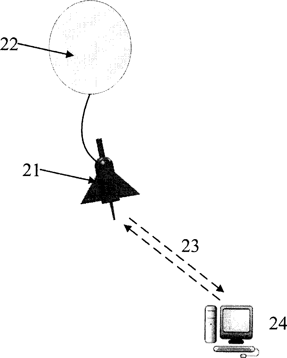
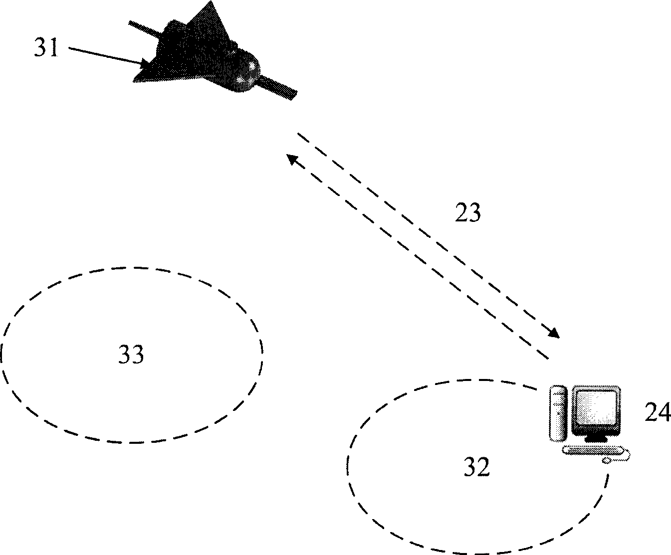
[0014] The process of airsonde lift-off is as follows: figure 2 As shown, the radiosonde (21) is carried by a balloon (22) filled with hydrogen (or other light gas) and lifted to an altitude of 30km to 40km, and the location and / or weather data carried by the radiosonde are obtained during the lifting process The device measures atmospheric data (including temperature, humidity, air pres...


PUM


Abstract

Disclosed is a radiosonde system with gliding function, which comprises: a device which can generate lift force with the help of gravity and / or wind power, a motion control device, an obtaining device and / or a weather data device, and a device which can transmit radiosonde data through a radio-frequency way. The radiosonde system with gliding function can generate the lift force with the help of the gravity and / or wind power after the lifting balloon is invalidated, and the motion control device can control the return lift position and other recovery positions. The radiosonde system with gliding function has functions that the system can explore over 40km height in the sky and can release at any position with safe recovery and initial position exploration and the like, and has the advantages that the exploration rang is wide, the reliability is high, and the cost is low and the like, thereby greatly enhancing applicability of the radiosonde.

Description

technical field [0001] The invention relates to a radiosonde system, in particular to a radiosonde system with gliding function. Background technique [0002] Synoptic observations in the upper atmosphere are made using radiosondes mounted on sounding balloons. The radiosonde is generally lifted from the ground to a height of 30km to 40km by a balloon filled with hydrogen (or other light gas). During the lifting process, the temperature, humidity, and pressure sensors carried by the radiosonde measure atmospheric temperature, humidity, pressure and other parameters; the radiolocation system (such as Loran-C or GPS system, etc.) Then the wind speed and wind direction and other parameters are calculated; the measured atmospheric parameters are sent back to the ground by the radio frequency transmitter; the balloon is designed to rise to a height of 30km to 40km according to the weight of the radiosonde, and then the balloon explodes and the sounding The instrument falls free...

Claims


Application Information

Patent Timeline
Patent Type & Authority Applications(China)
IPC IPC(8): G01W1/08
Inventor 王爱喜张来义李玉琦王洋
Owner 王爱喜
Learn More