
Refrigeration apparatus

A refrigeration device and refrigerant technology, applied in refrigerators, refrigeration components, refrigeration and liquefaction, etc., can solve the problems of insufficient defrosting capacity, prolonged defrosting time, and damage to comfort

Active Publication Date: 2009-02-18
DAIKIN IND LTD
View PDF1 Cites 4 Cited by
  • Summary
  • Abstract
  • Description
  • Claims
  • Application Information

AI Technical Summary

Problems solved by technology

In this way, in the reverse cycle defrosting operation, regardless of whether there is a high-stage side compressor, only the low-stage side compressor can be operated, so the defrosting capacity cannot be fully utilized, resulting in longer defrosting time
The result is a loss of comfort during heating operation

Method used


Image

  • Refrigeration apparatus
  • Refrigeration apparatus
  • Refrigeration apparatus

Examples


Embodiment approach 1

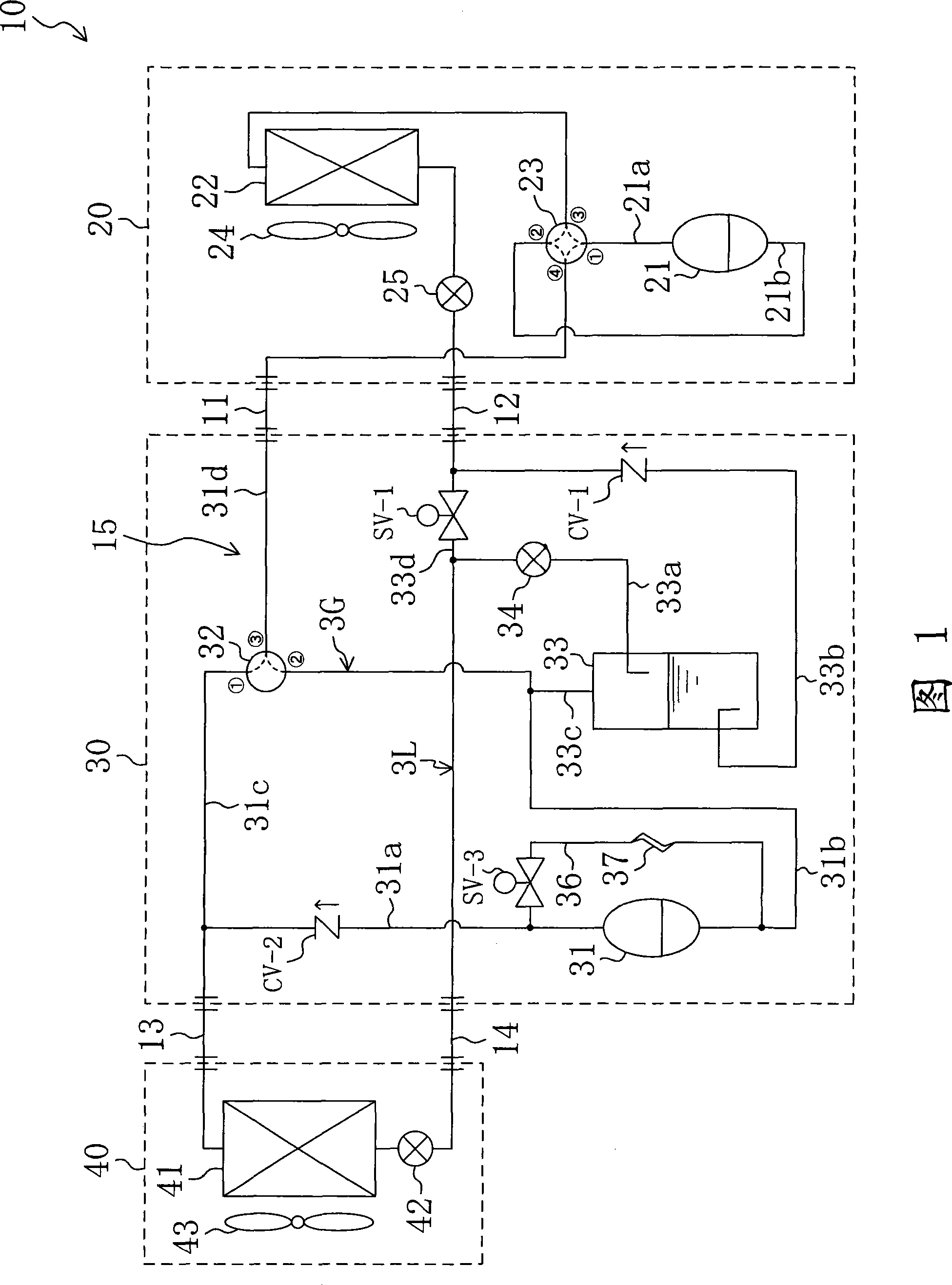
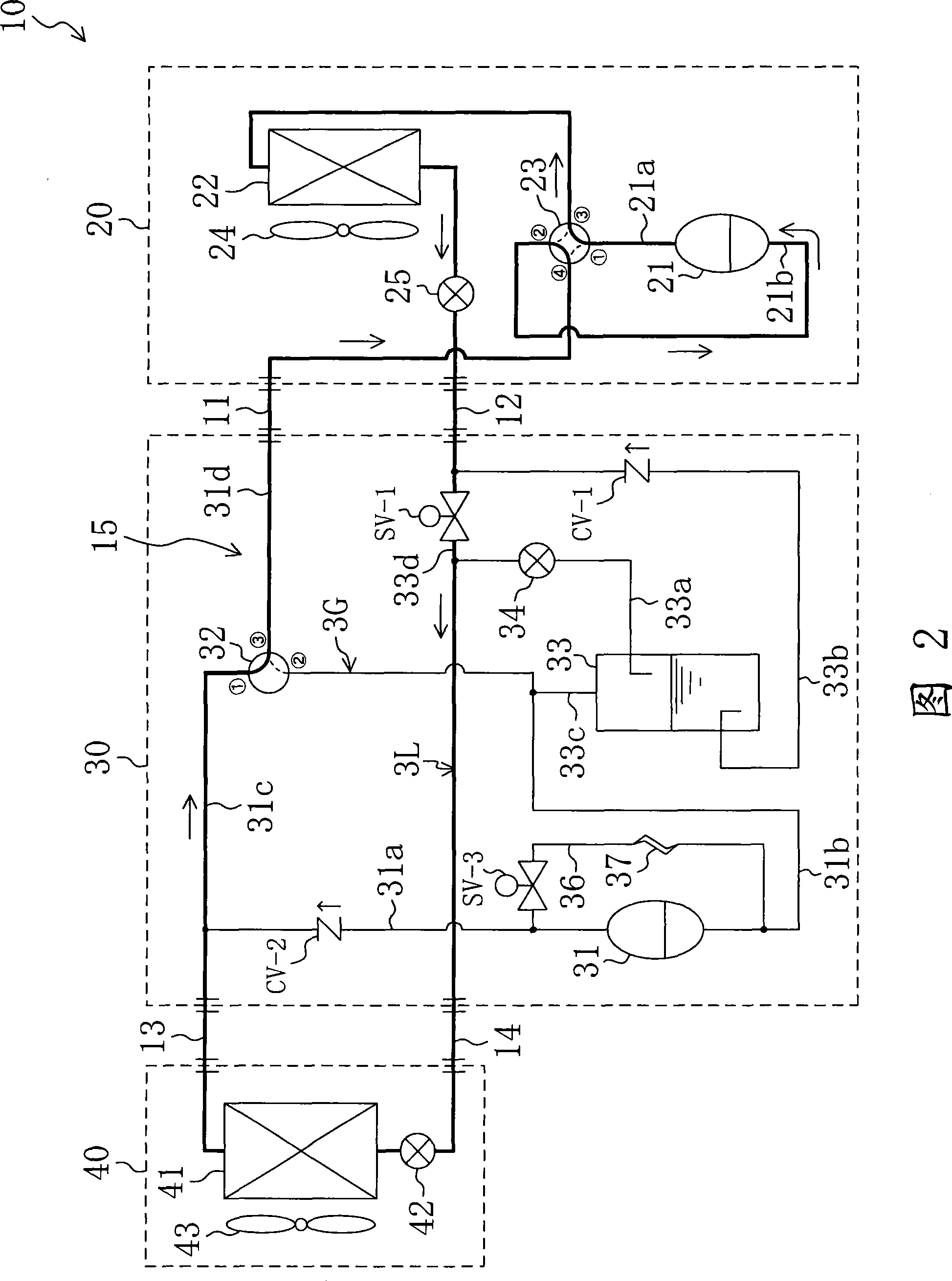
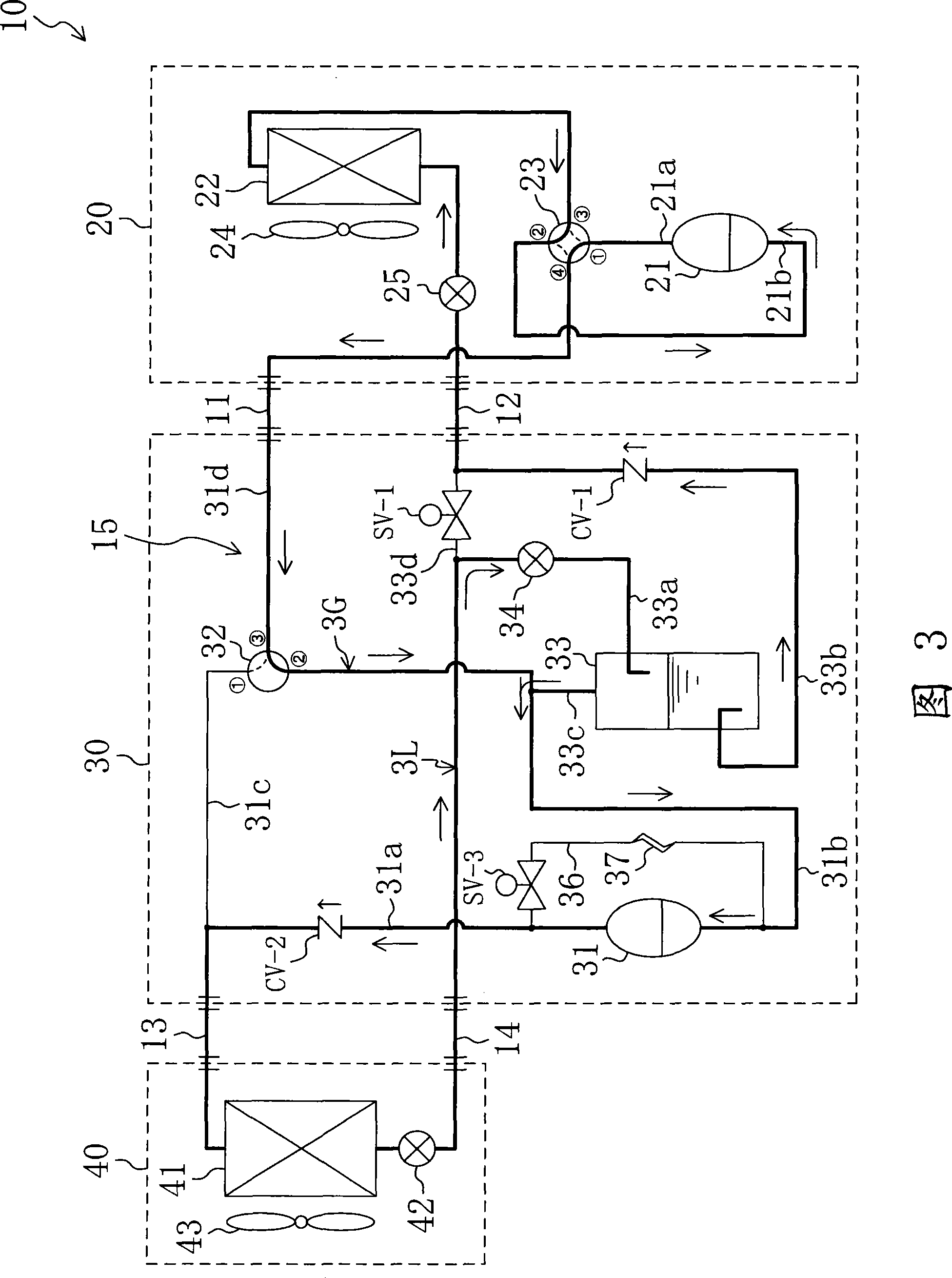
The refrigeration system according to Embodiment 1 constitutes a heat pump air conditioner 10 capable of cooling operation, heating operation, and defrosting operation. As shown in FIG. 1 , this air conditioner 10 includes an outdoor unit 20 installed outdoors, an optional unit 30 constituting an extension intermediate unit, and an indoor unit 40 installed indoors.

[0045] The outdoor unit 20 is connected to the selection unit 30 through the first connecting pipe 11 and the second connecting pipe 12 . In addition, the indoor unit 40 is connected to the selection unit 30 through the third connecting pipe 13 and the fourth connecting pipe 14 . In this way, the respective units 20 , 30 , and 40 are connected to form the refrigerant circuit 15 . The refrigerant circuit 15 is configured to circulate a refrigerant to perform a vapor compression refrigeration cycle.

[0046] In addition, the selection unit 30 constitutes a power-up unit of the original split-type air conditioner. S...

Embodiment approach 2

As shown in FIG. 5 , the refrigerating apparatus of the second embodiment is an apparatus in which the selector unit 30 is provided with a duct heater 38 in addition to the air conditioner 10 of the first embodiment.

[0082] Specifically, the pipe heater 38 is provided on the side of the liquid inflow pipe 33 a closer to the gas-liquid separator 33 than the selection-side expansion valve 34 . The pipe heater 38 constitutes a heating means for heating the refrigerant flowing through the liquid inflow pipe 33a during the second defrosting operation.

[0083] At this time, during the second defrosting operation, the liquid refrigerant flowing from the outdoor unit 20 to the liquid inflow pipe 33a and branched to the gas-liquid separator 33 side is heated by the pipe heater 38 to become a gas-liquid two-phase state. The refrigerant. The refrigerant in the gas-liquid two-phase state flows into the gas-liquid separator 33 . Accordingly, the ratio of the amount of gaseous refrigera...


PUM


Abstract

The invention discloses a refrigeration device. Between an outdoor unit (20) having a lower stage side compressor (21) and an indoor unit (40), an option unit (30) having a higher stage side compressor (31) and a gas / liquid separator (33) is provided. During a defrost operation, an outdoor heat exchanger (22) is defrosted by refrigerant delivered from the lower stage side compressor (21) and refrigerant of the gas / liquid separator (33) is sucked into the higher stage side compressor (31) and delivered to the suction side of the lower stage side compressor (21). The option unit (30) is provided with an injection pipe (36) for returning a part of refrigerant delivered from the higher stage side compressor (31) to the suction side of the higher stage side compressor (31). Consequently, refrigerant flowing from the gas / liquid separator (33) to the higher stage side compressor (31) is gasified by high temperature delivery refrigerant.

Description

technical field [0001] The invention relates to a refrigerating device, in particular to a refrigerating device which uses a gas-liquid separator of an intermediate-pressure refrigerant and performs a double-stage compression and double-expansion refrigeration cycle. Background technique [0002] Conventionally, refrigerating equipment, hot water supply equipment, and the like that perform a refrigeration cycle in a refrigerant circuit have been known. For example, Patent Document 1 discloses an air conditioner as a refrigeration device that cools and heats a room by reversibly circulating a refrigerant in a refrigerant circuit. [0003] Specifically, in the air conditioner of Patent Document 1, by switching the four-way switching valve, it is possible to perform a refrigeration cycle in which the refrigerant discharged from the compressor flows to the outdoor heat exchanger during cooling, and to perform a cooling cycle in which the refrigerant discharged from the compresso...

Claims


Application Information

Patent Timeline
IPC IPC(8): F25B1/00F25B1/10F25B43/00
CPCF25B2400/23F25B2400/13F25B47/02F25B13/00F25B2313/02731F25B2600/0261F25B2313/006F25B2313/02741F25B1/10F25B1/00F25B43/00
Inventor 山田昌弘
Owner DAIKIN IND LTD
Learn More