Lenticular lens array element

A lens array and component technology, applied in the direction of lenses, optical components, instruments, etc.

Active Publication Date: 2009-02-18
AU OPTRONICS CORP
View PDF0 Cites 5 Cited by
  • Summary
  • Abstract
  • Description
  • Claims
  • Application Information

AI Technical Summary

Problems solved by technology

This surface reflection can cause many problems depe

Method used


Image

  • Lenticular lens array element
  • Lenticular lens array element
  • Lenticular lens array element

Examples


Embodiment Construction

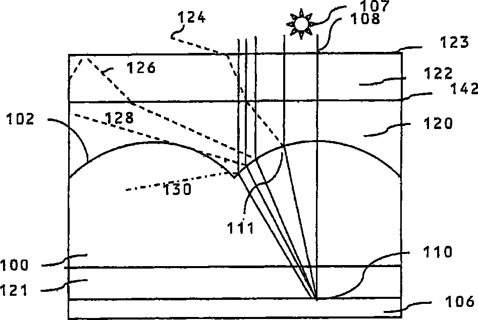
[0162]The various arrangements described below contain a number of common building blocks. Common components are given the same reference numbers. For the sake of brevity, descriptions of common components are not repeated, but any discussion of a component applies to all embodiments in which it appears.

[0163] Here, first, a directional printing image display apparatus using a lens member according to the present invention will be described.

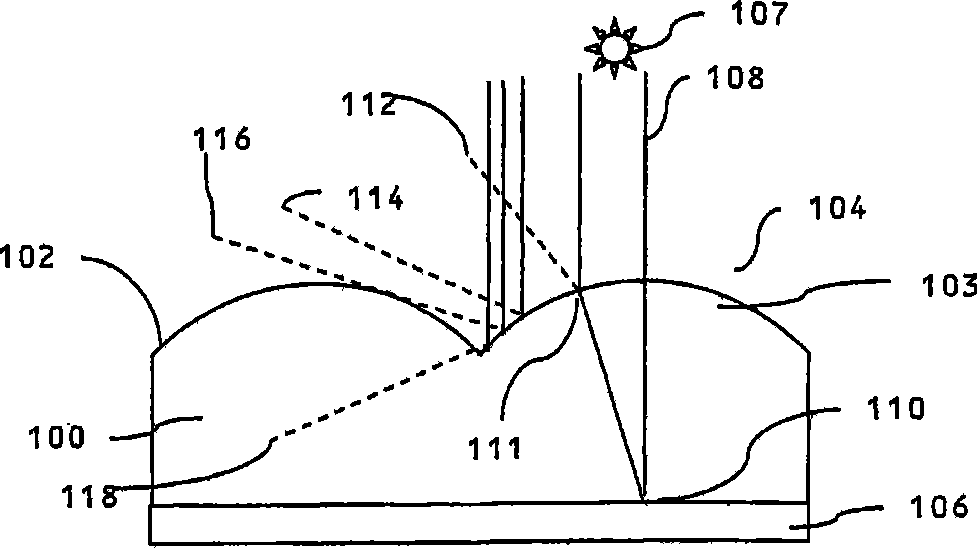
[0164] figure 1 A directional printed image display device utilizing a known type of lens array is shown. A lens structure comprises a substrate 100 whose front surface 102 has a surface relief shaped as a cylindrical lens array surface. The front surface 102 constitutes an interface between the substrate 100 and air 104 . Each of the lens surfaces can thus be regarded as a section of the surface relief, which provides a lens effect, and the lens member constitutes a lens array.

[0165] In this specification, the term "cylindric...


PUM


Abstract

A lens element comprises: a rear substrate having a front surface provided with a surface relief having a plurality of zones each capable of providing a lens effect; a front substrate disposed in front of the rear substrate and having a rear surface provided with a surface relief having a plurality of zones each capable of providing a lens effect, the zones of the surface reliefs provided on the rear substrate and the front substrate having the same spatial arrangement over the area of the lens element; and solid or liquid, isotropic, intermediate material disposed between the front surface of the rear substrate and the rear surface of the front substrate, the intermediate material having a refractive index different from the refractive index of each of the rear substrate and the front substrate. This construction reduces the degree of Fresnel reflection which will otherwise degrade the optical performance.

Description

technical field [0001] The present invention relates to a lens component, which is composed of a substrate, the surface of the substrate has surface relief which can provide a lens effect. For example, the surface relief can be shaped as a lens array surface or as a Fresnel lens depending on the field of application. Background technique [0002] In one field of application, the lens structure may constitute a lens array for a printed image display device having a plurality of printed images wherein the stripes of each printed image are interleaved. In another field of application, the lens structure may constitute a lens array for a display device having an array of pixels capable of displaying an interlaced image using a spatial light modulator. In these applications, the lens array is in use placed over multiple printed images or spatial light modulators. The lens array directs light from each printed image into an individual viewing window. This can produce many diffe...

Claims


Application Information

Patent Timeline
IPC IPC(8): G02B3/00G02B27/22G03B21/62G02B30/27
CPCG02B27/2214G02B3/0062G02B3/0031G03B21/625G02B3/005G02B3/0075G02B30/27G02B27/10
Inventor 葛瑞汉·约翰·伍德凯吉强纳森·哈洛德
Owner AU OPTRONICS CORP
Why Eureka
Try Eureka