
Axial plunger type variable capacity pump

A plunger type, variable displacement pump technology, applied in the field of variable displacement pumps, can solve the problems of large energy consumption, slow return speed, slow righting speed of swash plate, etc., and achieve reasonable force application, rapid adjustment and fast response Effect

Inactive Publication Date: 2009-02-25
UNION PLASTIC HANGZHOU MACHINERY +2
View PDF0 Cites 5 Cited by
  • Summary
  • Abstract
  • Description
  • Claims
  • Application Information

AI Technical Summary

Problems solved by technology

However, due to the small force of the return spring, the righting speed of the swash plate is slow; the actual pressure of the oil discharge port is reduced through the natural oil discharge of the oil discharge valve, and the response time of the proportional pressure valve and the proportional flow valve is long, and there is a lag period , and digital control cannot be realized, resulting in the disadvantages of the traditional axial piston variable pump, such as inability to accurately sense the displacement change of the variable pump, slow return speed, large energy consumption, and low efficiency.

Method used


Image

  • Axial plunger type variable capacity pump
  • Axial plunger type variable capacity pump
  • Axial plunger type variable capacity pump

Examples


Embodiment 1

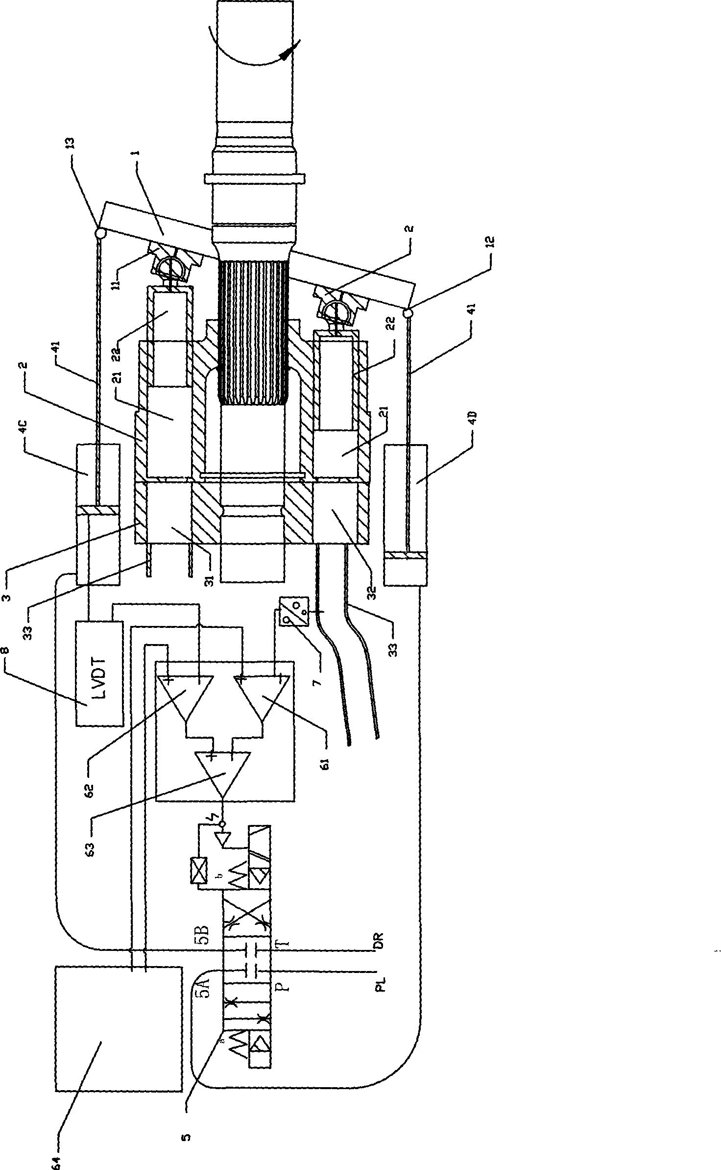
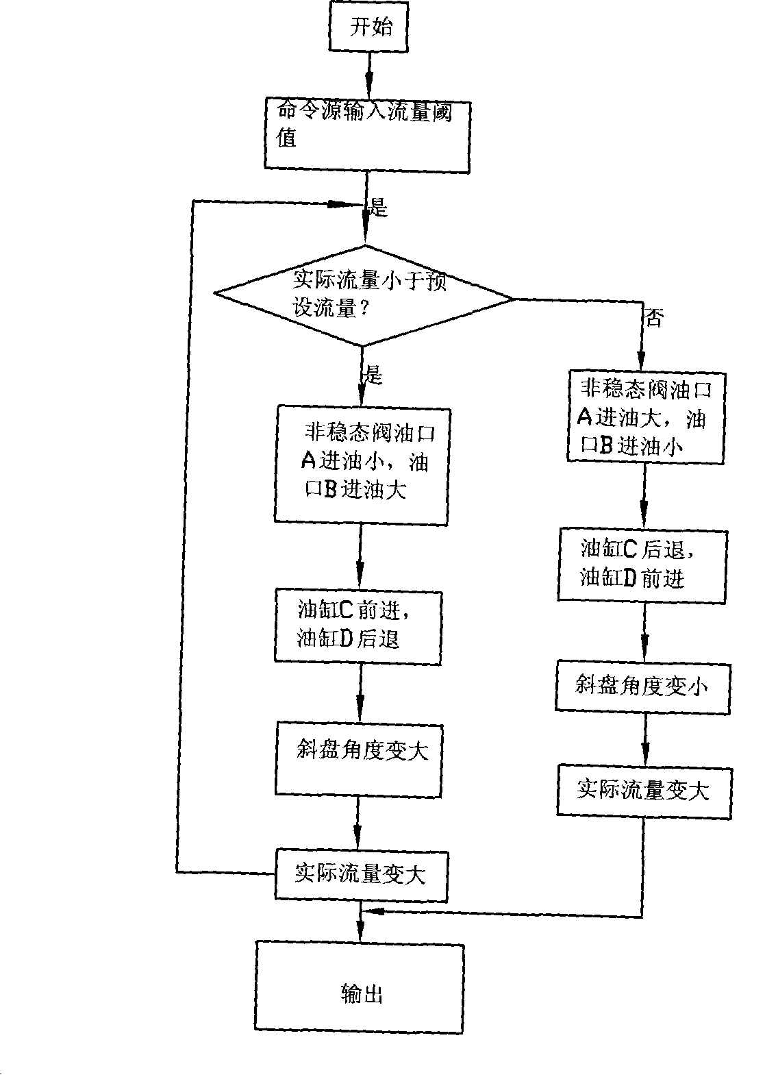
[0041] refer to figure 1 , figure 2 :

[0042] The axial piston type variable displacement pump described in the present invention includes:

[0043] The swash plate 1 hinged on the swash plate seat in a manner that can change the relative inclination angle;

[0044] A rotatable plunger cylinder 2, the cylinder 2 is arranged with an axial plunger hole 21 along the circumferential direction; the front part of the plunger hole 21 is provided with a plunger 22, and the plunger 22 The front end of the swash plate is connected to a sliding shoe 11 that can slide on the surface of the swash plate 1 in the form of a ball joint;

[0045] The rear part of the plunger cylinder 2 is connected to an oil distribution pan 3, and the oil suction port 31 and the oil discharge port 32 are arranged on the oil distribution pan 3, and the oil suction port 31 and the oil discharge port 32 are connected to the The rear part of the plunger hole 21; the oil suction port 31 and the oil discharge ...

Embodiment 2

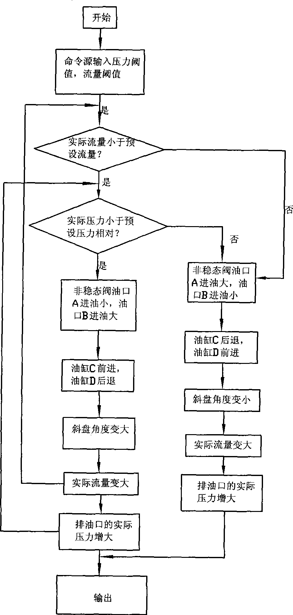
[0060] refer to figure 1 , image 3 :

[0061] The difference between embodiment two and embodiment one is:

[0062] The negative input terminal of the amplifier 63 is connected to the second comparator 62, and the positive and negative input terminals of the second comparator 62 are respectively connected to the threshold value command source 64 and a device for measuring the tilt displacement of the swash plate 1. Displacement sensor 8, the threshold command source 64 outputs the flow threshold set according to user needs, the displacement sensor 8 outputs a displacement signal corresponding to the actual flow, and the second comparator 62 outputs the flow threshold and the actual flow comparison results.

[0063] The controller is provided with a mode selection module, and the mode selection module controls the amplifier 63 to select a pressure mode or a flow mode or a flow-pressure mode to control the unsteady valve;

[0064] The amplifier 63 selects the flow-pressure ...


PUM


Abstract

The invention relates to an axial plunger-type variable pump which comprises a swash plate, a slipper, a plunger, a plunger cylinder body and a fuel distributor. A forward tipping part and a backward bending part of the swash plate are respectively connected with a push rod of a push action cylinder; the inner cavities of two push action cylinders are respectively communicated with two output ports of an unsteady valve; the unsteady valve is controlled by a controller; the controller comprises a first comparator, an amplifier and a threshold command source; and the amplifier is connected with a second comparator. The invention has the advantages that the accurate change of delivery capacity of the variable pump can be perceived; the angle of the swash plate is rapidly controlled; and the energy consumption is low, and the efficiency is high.

Description

technical field [0001] The invention relates to a variable displacement pump, in particular to an axial plunger type variable displacement pump. Background technique [0002] Axial piston variable displacement pumps are widely used in various hydraulic systems due to their small size, light weight, high power density, and easy control. [0003] The traditional axial piston variable displacement pump consists of a variable displacement pump with an inclined swash plate and a variable adjustment mechanism. The adjustment mechanism includes a proportional pressure valve, a proportional flow valve and a return spring installed on the swash plate. When the variable displacement pump When the pressure at the oil discharge port is lower than the pressure threshold, the proportional pressure valve and proportional flow valve output pressure and flow to the system according to the set value, resulting in an increase in pressure difference and flow difference, pushing the swash plate ...

Claims


Application Information

Patent Timeline
IPC IPC(8): F04B1/16F04B49/12F04B53/00F04B49/00
Inventor 韩志翔
Owner UNION PLASTIC HANGZHOU MACHINERY
Learn More