Process for the fabrication of a hole

A pulse length, laser technology, applied in the field of hole processing, can solve the problems of small average power of laser pulse, expensive, time-consuming, etc.

Inactive Publication Date: 2009-02-25
SIEMENS AG
View PDF14 Cites 7 Cited by
  • Summary
  • Abstract
  • Description
  • Claims
  • Application Information

AI Technical Summary

Problems solved by technology

[0009] The use of ultrashort laser pulses is very time-consuming due to their low average power and is therefore expensive

Method used


Image

  • Process for the fabrication of a hole
  • Process for the fabrication of a hole
  • Process for the fabrication of a hole

Examples


Embodiment Construction

[0025] Description of parts with holes

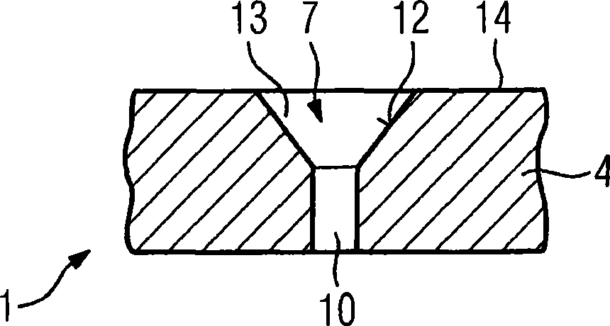
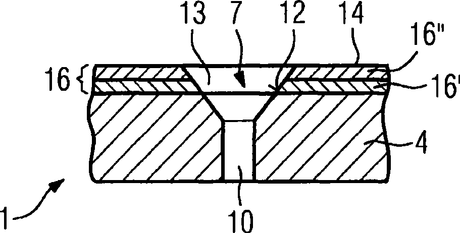
[0026] figure 1 Part 1 is shown with holes 7 .

[0027] The component 1 is formed from a substrate 4 (for example a casting or a DS or SX component).

[0028] The substrate 4 can be metallic and / or ceramic. Especially in turbine components, such as turbine moving blades 120 or turbine guide vanes 130 ( FIGS. 16 , 17 ), heat shield elements 155 ( Figure 18 ) and other housing components, the substrate 4 is made of a nickel-based, cobalt-based or iron-based superalloy. On turbine blades for aircraft, the substrate 4 is made, for example, of titanium or a titanium-based alloy.

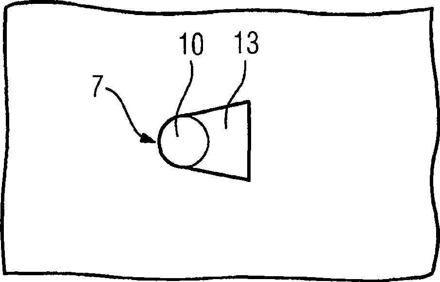
[0029] The substrate 4 has holes 7 which are preferably through-holes. But it can also be a blind hole. The hole 7 comprises a lower region 10 and an upper region 13, the lower region 10 starting from the inner side of the component 1 and preferably symmetrical (such as circular, oval or rectangular) , and the upper region 13 is optionally formed as a dif...


PUM


Abstract

Conventional methods for producing a hole in a component are time-consuming and costly as special lasers featuring short laser pulse durations are used. In the inventive method, the laser pulse durations are varied, short laser pulse durations being utilized only in the area to be removed in which an influence on the penetration behavior and discharge behavior is noticeable while longer pulse durations of >0.4ms are used. This is the case for the inner surface (12) of a diffuser (13) of a hole (7), for example, which can be produced very accurately by means of short laser pulse durations.

Description

technical field [0001] The invention relates to a method for producing bores according to claim 1 , in which a bore is produced in a component by means of a pulsating energy beam. Background technique [0002] On many components, especially on castings, erosions like recesses or through-holes have to be produced later. Especially on turbomachine components which have film cooling holes for cooling, the holes are added later after the component has been produced. [0003] Such turbomachine components often also have layers, such as metallic layers or intermediate layers and / or ceramic outer layers. The film cooling holes must then be produced through the layer and substrate (casting). [0004] US-PS 6,172,331 and US-PS 6,054,673 disclose a laser drilling method for introducing holes in layer systems, in which ultrashort laser pulse lengths are used. A single laser pulse length is selected from a defined range of laser pulse lengths and the entire hole is thereby generated....

Claims


Application Information

Patent Timeline
Patent Type & Authority Applications(China)
IPC IPC(8): B23K26/38B23K26/06
CPCB23K26/063B23K26/0639B23K26/0665B23K26/0648B23K26/388B23K26/0622B23K26/064B23K26/389
Inventor T·贝克S·塞特加斯特
Owner SIEMENS AG
Why Eureka
Try Eureka